EasyManua.ls Logo

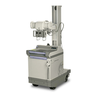
GE AMX-II

GE AMX-II
223 pages
To Next Page IconTo Next Page
To Previous Page IconTo Previous Page
Loading...
GENERAL
ELECTRIC
MEDICAL
SYSTEMS
AMX-il
X-RAY
UNIT
6-978
10.
11.
12.
13.
NOTE:
14.
15.
16.
17.
18.
19.
20.
SM
A
0654E
Re-energize
charger.
Adjust
AC
input
voltage
for
a
charger current
no
more
than
3.0
DC
amps.
After
10
minutes
into
charging
period
check
voltage
of
each
cell
using
digital
voltmeter.
Voltage
should
be
between
1.2
and
1.55
volts.
If
any
cell
is
outside
this
range
stop
charging
procedure
and
replace
the
cell
group
under
terms
of
warranty.
If
a
cell
group
is
replaced,
start
over
at
Step
1
of
this
section.
For
protection,
place
the
furnished
red
insulating
boards
over
the
top
of
the
battery.
Temporarily
secure
with
masking
tape.
:
Record
charge
input
current
at
1/2
hour
intervals.
Adjust
AC
input
up
to
a
maximum
of
125
volts
to
maintain
DC
charge
current
between
2.0
and
3.0
amps.
This
charge
procedure
may
be
discontinued
overnite
without
having
to
begin
at
Step
1
the
following
day.
Turn
charger
ON
and
continue
with
readings
as
per
Step
13.
Continue
charging
and
recording
on
1/2
hour
intervals
for
a
maximum
of
8.0
hours
from
the
inita-
tion
of
Step
10
-
or
until
a
battery
voltage
of
131
to
132
V
is
achieved
-
whichever
comes
first.
If
8.0
hours,
continue
with
Step
15.
If
131
volts,
skip
to
Step
16.
At
the
end
of
8.0
hours
from
Step
10
with
battery
voltage
less
than
131
V;
adjust
line
voltage
for
a
reduced
charge
current
of
1.3
amperes.
Continue
at
this
rate,
recording
on
1/2
hour
intervals,
until
a
battery
voltage
of
131
to
132
is
realized.
When
battery
voltage
reaches
131
to
132
V,
slowly
adjust
441R30
clockwise
until
the
charger
stops
and
the
charge
complete
lamp
lights.
Turn
OPERATOR'S
KEY
switch
and
Main
Power
Circuit
Breaker
OFF.
Disconnect
charger
plug
from
wall
outlet.
Move
the
white
lead
from
4A1-2
to
4A1-17
and
the
black
lead
that
goes
to
4
CR5
bridge
from
4A1-8
to
4A1-18.
If
the
charger
board
does
not
have
terminals
4A1-17
and
4A1-18
connect
a
jumper
(No.
16
AWG
wire
or
larger
capable
of
carrying
3
amps)
across
terminal
4A1-2.
This
by-passes
4CR6
to
allow
battery
charging
even
though
the
automatic
cut-off
has
shut
off
4CR6.
Connect
the
battery
charger
plug
to
variable
autotransformer
in
AC
line.
Turn
OPERATOR’S
KEY
switch
to
CHARGE
and
main
power
circuit
breaker
on
ON.
Adjust
variable
autotransformer
in
AC
line
for
a
charge
current
of
1.3
amperes.
Continue
charging
and
recording
change
current
on 1/2
hour
intervals
until
a
total
of
21.0
ampere-
hours
is
accrued.
During
this
overcharge
i
.terval
battery
voltage
should
rise
from
131
to
a
minimum
of
135
volts.
Adjust
AC
line
input
to
maintain
1.3
ampere
charging
current.
When
21.0
ampere
hours
is
accrued,
and
with
battery
still
on
charge,
measure
voltage
of
each
cell
with
digital
voltmeter.
All
cells shall
read
at
least
1.50
volts.
Record
individually
all
voltages
in
Battery
Service
Log
F3560.
If
any
cell
reads
less
than
1.50
voits
that
cell
group
should
be
replaced
following
established
warranty
procedures.
Use
F
3560
for
record
information.
3-19

Related product manuals