Installation Instructions
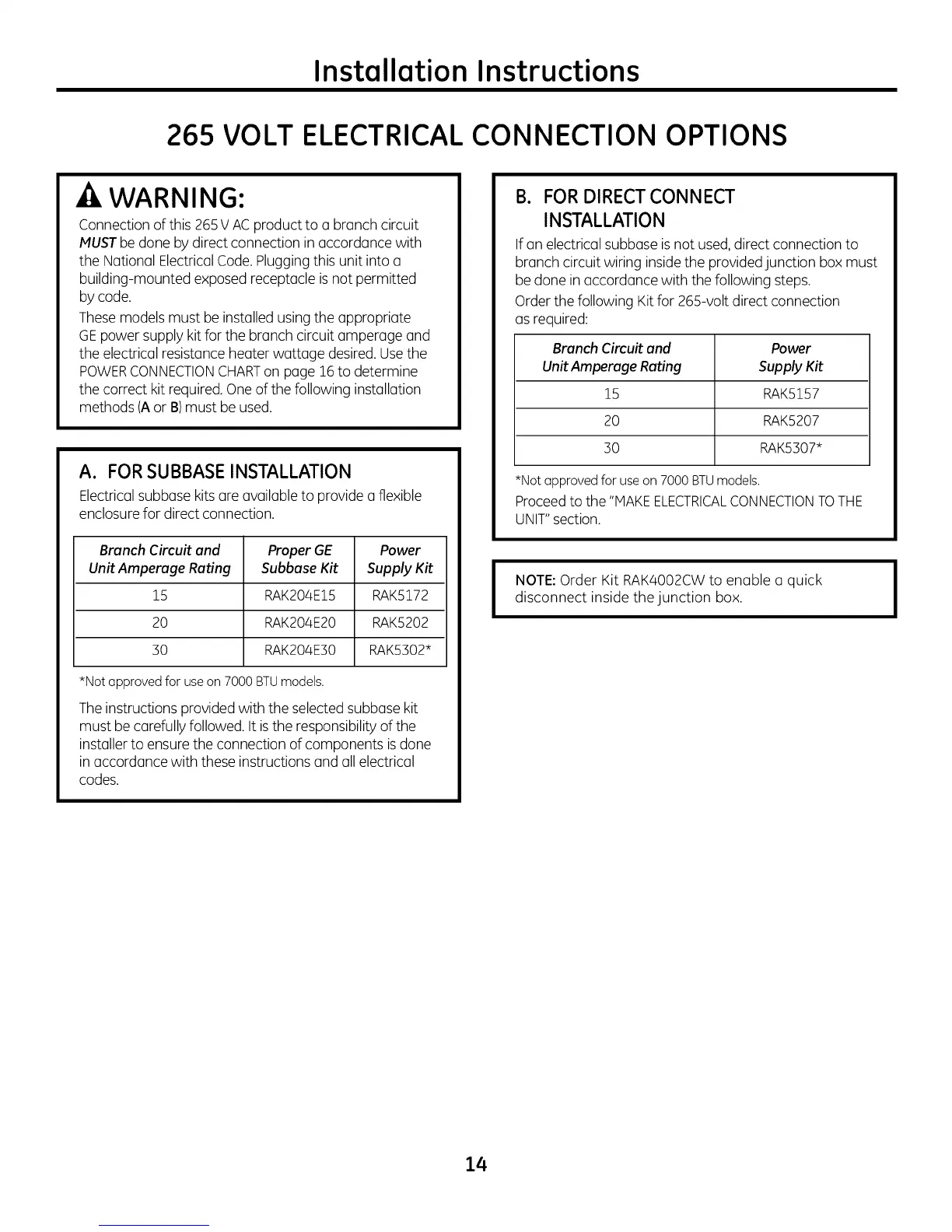
265 VOLT ELECTRICAL CONNECTION OPTIONS
WARNING:
Connectionof this 265V ACproduct to a branch circuit
MUSTbe done bydirect connection in accordance with
the National ElectricalCode. Pluggingthis unit into a
building-mounted exposed receptacle is not permitted
by code.
These models must be installed using the appropriate
GEpower supply kit for the branch circuit amperage and
the electrical resistance heater wattage desired.Usethe
POWERCONNECTIONCHARTon page 16to determine
the correct kit required. One of the following installation
methods (Aor B)must be used.
A. FOR SUBBASE INSTALLATION
Electricalsubbase kits are availableto provide a flexible
enclosurefor direct connection.
Branch Circuit and Proper GE Power
Unit Amperage Rating Subbase Kit Supply Kit
15 RAK204E15 RAK5172
20 RAK204E20 RAK5202
30 RAK204E30 RAK5302*
*Not approved for useon 7000 BTUmodels.
The instructions provided with the selected subbase kit
must be carefully followed. It isthe responsibility of the
installer to ensure the connection of components is done
in accordance with these instructions and all electrical
codes.
I
B. FOR DIRECTCONNECT
INSTALLATION
If an electricalsubbase is not used,direct connection to
branch circuit wiring insidethe providedjunction box must
be done in accordance with the following steps.
Orderthe following Kit for 265-volt direct connection
asrequired:
Branch Circuit and Power
Unit Amperage Rating Supply Kit
15 RAK5157
20 RAK5207
:30 RAK5307*
*Not approved for use on 7000 BTUmodels.
Proceed to the "MAKE ELECTRICALCONNECTION TO THE
UNIT" section.
NOTE:Order Kit RAK4002CW to enable a quick
disconnect inside the junction box.
I
14