– 17 –
TO SURFACE
UNITS
EOC
TO LOWER OVEN
THERMOSTAT
SW4 LATCH
NC
NO
COM
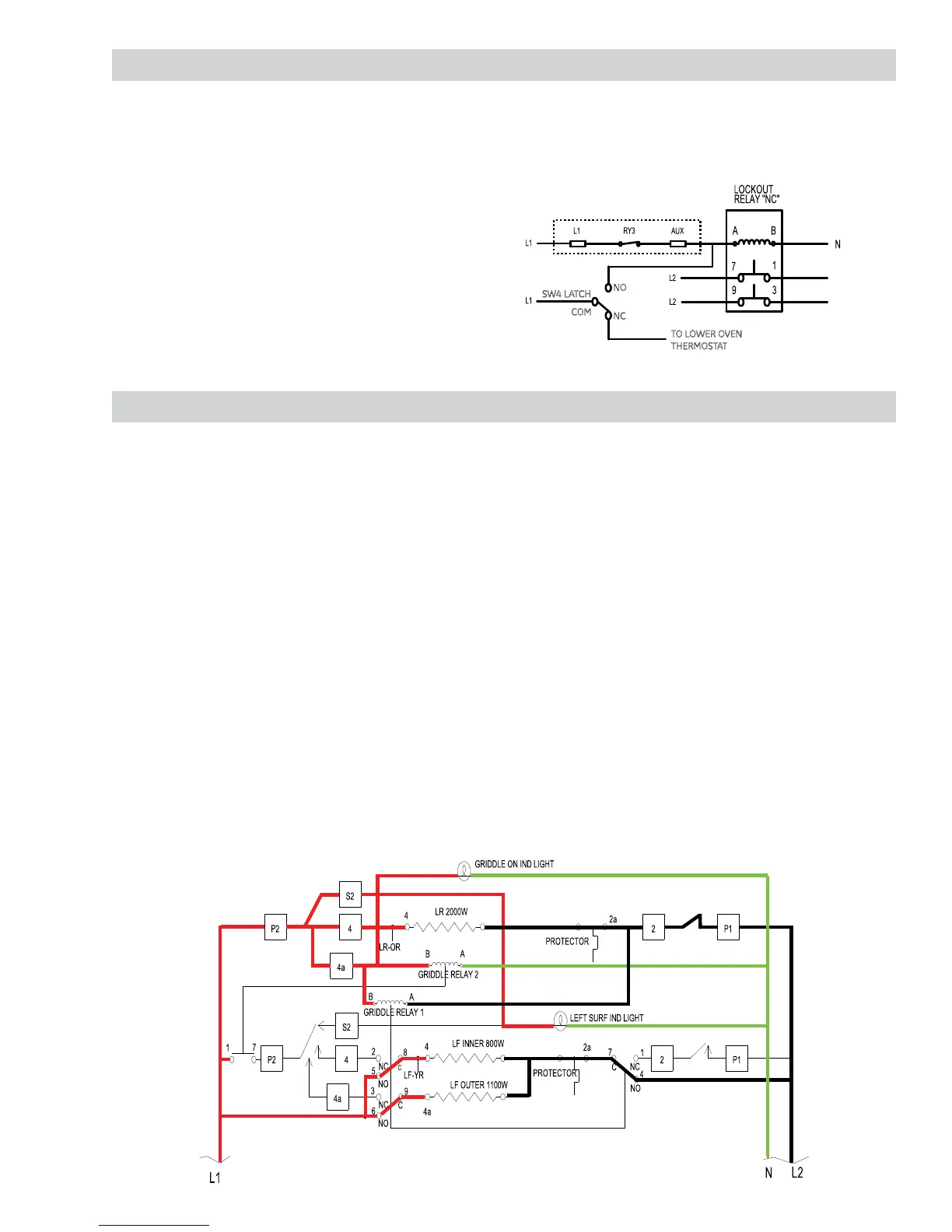
Griddle Operation
The griddle, placed over the left side surface
elements, can be heated using the rear element
only or both the front and rear elements at the
same time. Two relays are used to allow only the left
rear infi nite heat switch to operate both front and
rear elements.
When the left rear control is turned clockwise to
select griddle:
P2 closes to 4, supplying L1 voltage to the left •
rear element.
P2 closes to S2, supplying L1 voltage to the left •
surface indicator light.
P2 closes to 4a, supplying L1 voltage to the •
griddle ON indicator light, relay 1 and relay 2.
Relay 2 (now operating on 120VAC) disconnects •
L1 voltage from the left front control.
Range Lockout Relay
The range lockout feature (on some models), allows
the user to lockout the surface units, upper oven,
and control panel so they cannot be activated.
When the control is set for RANGE LOCKOUT, the
control deactivates the upper oven and control
panel and energizes the lockout relay that locks out
the surface units so they cannot be activated. (See
Control Features.)
The control RY3 relay will close and complete the
circuit that supplies the voltage to the lockout relay.
The relay is also energized when the oven door is
locked (COM to NO closed). When energized, the
lockout relay will open contacts 7 to 1 and 9 to 3,
disconnecting L2 from the surface units.
Relay 1 (now operating on 240VAC) simultaneously:
Disconnects the left front control element •
cycling contacts, P1 to 2, and connects both left
front elements directly to L2.
Connects L1 voltage directly to both left front •
elements.
Contacts P1 to 2, on the left rear control, now cycle
L2 voltage to both the left rear element and to relay
1, which now operates both left front elements.
Note: With the griddle turned off and the left rear
hot surface light on (glass temperature above
150°F), 27 VAC will be applied to relay 2 and 97 VAC
will be applied to relay 1. During this time, both
relays may produce a slight hum/vibration. Neither
relay will be operating. The hum/vibration will cease
once the hot light switch contacts 1b to 2b open.
 Loading...