– 22 –
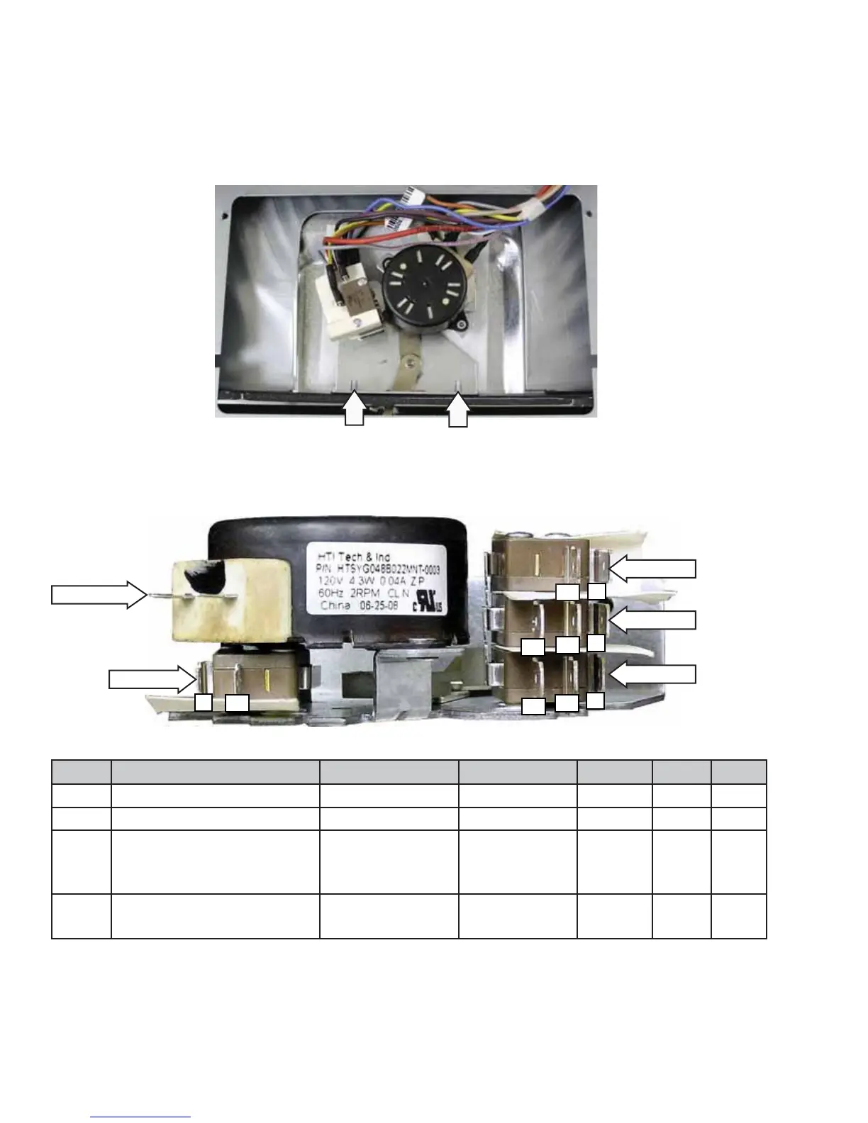
Switch #3
Switch #4
Switch #2
Switch #1
C
C
C
NC
NO
NO
NO
NC
NO
C
Lock Motor
Door Lock Assembly (removed, rear view shown)
Caution: It is possible to reconnect the switch wiring incorrectly to the lock assembly. When reconnecting
the wiring, make sure it is properly connected to the lock assembly before turning the power back on.
Switch Function Door UnLocked Door Locked C NO NC
1 Door Lock C - NO open C - NO closed Yellow Gray N/A
2 Door Unlock C - NO closed C - NO open Yellow Orange N/A
3 Cooling Fan Motor Speed
Hi speed in clean, Low speed
in other modes
C - NO closed
C - NC open
C - NO open
C - NC closed
Gray/Red Black Blue
4 Lower oven and all surface
unit lockout in Clean cycle
C - NO closed
C - NC open
C - NO open
C - NC closed
Red Violet Brown
Door Lock Assembly (top view shown with insulation and cover removed)
Lock Assembly Removal
The lock assembly is attached to the front of the range by two T-15 Torx screws. To replace the door lock it
is necessary to place the control panel in the service position (See
Control Panel.), remove the lock assembly
insulation, and two 1/4-in. hex-head screws and the lock assembly cover.
 Loading...