– 23 –
Tab
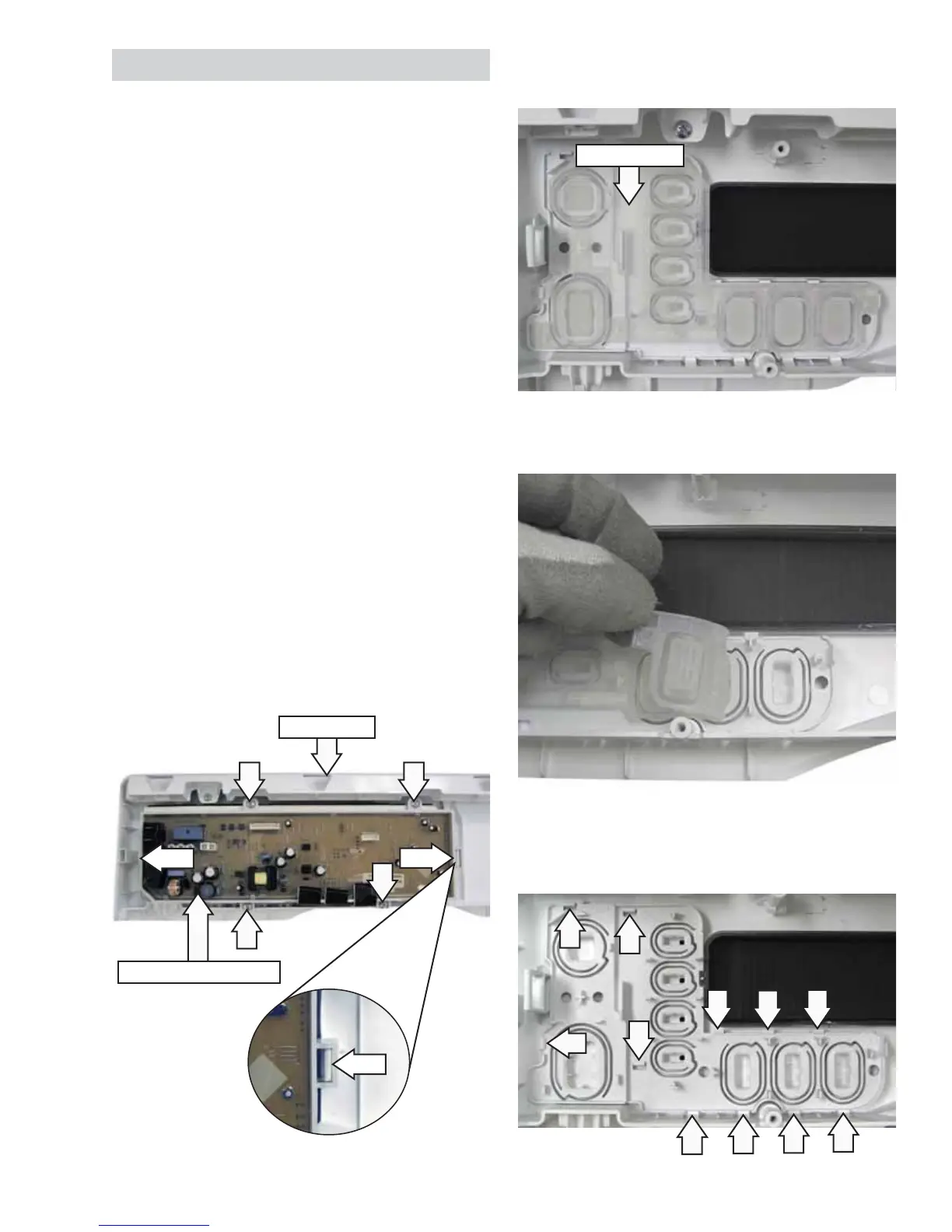
Control Board Assembly
Tab
Tab
Control Panel
7. Carefully peel back the button overlay and
remove it from the control panel.
8. Release the 11 tabs that attach the button
frame to the control panel, then lift the frame
from the panel.
Note: In the next step, the button overlay is inserted
into the rear of the buttons on the control panel.
Button Overlay
Control Board
The control board is mounted in a housing that
is attached to the inside of the control panel. The
control board and housing are replaced as an
assembly. The control board assembly is held in
place by 4 Phillips-head screws and 2 tabs.
The control will shut down 15 minutes after the last
button press or the end of the cycle.
To remove the control board:
Remove the control panel. (See 1. Control Panel.)
Pull the cycle knob off. Note the alignment of the 2.
"D" shaft when installing the knob.
Place the control panel, face down, on a 3.
protective surface.
Remove the 4 Phillips-head screws that attach 4.
the control board assembly to the control panel.
Press each of the 2 tabs inward, 1 on each side, 5.
and lift the control board assembly from the
control panel.
Operation of the control board can be checked by
using the service test mode. (See Service Mode.)
Specifi c failures associated with the control board
can initiate error codes tS, t0, dE, od, HE, FE, bE2,
3E1, and 3E2. (See Error Codes.)
 Loading...