– 24 –
Front Panel
Removal of the front panel provides access to the
drum support and blower wheel. The front panel
is inserted into 3 hooks attached to the bottom of
the cabinet and held in place with 6 Phillips-head
screws. The door switch is attached to the front
panel.
To remove the front panel:
Remove the top panel. (See 1. Top Panel.)
Remove the control panel. (See 2. Control Panel.)
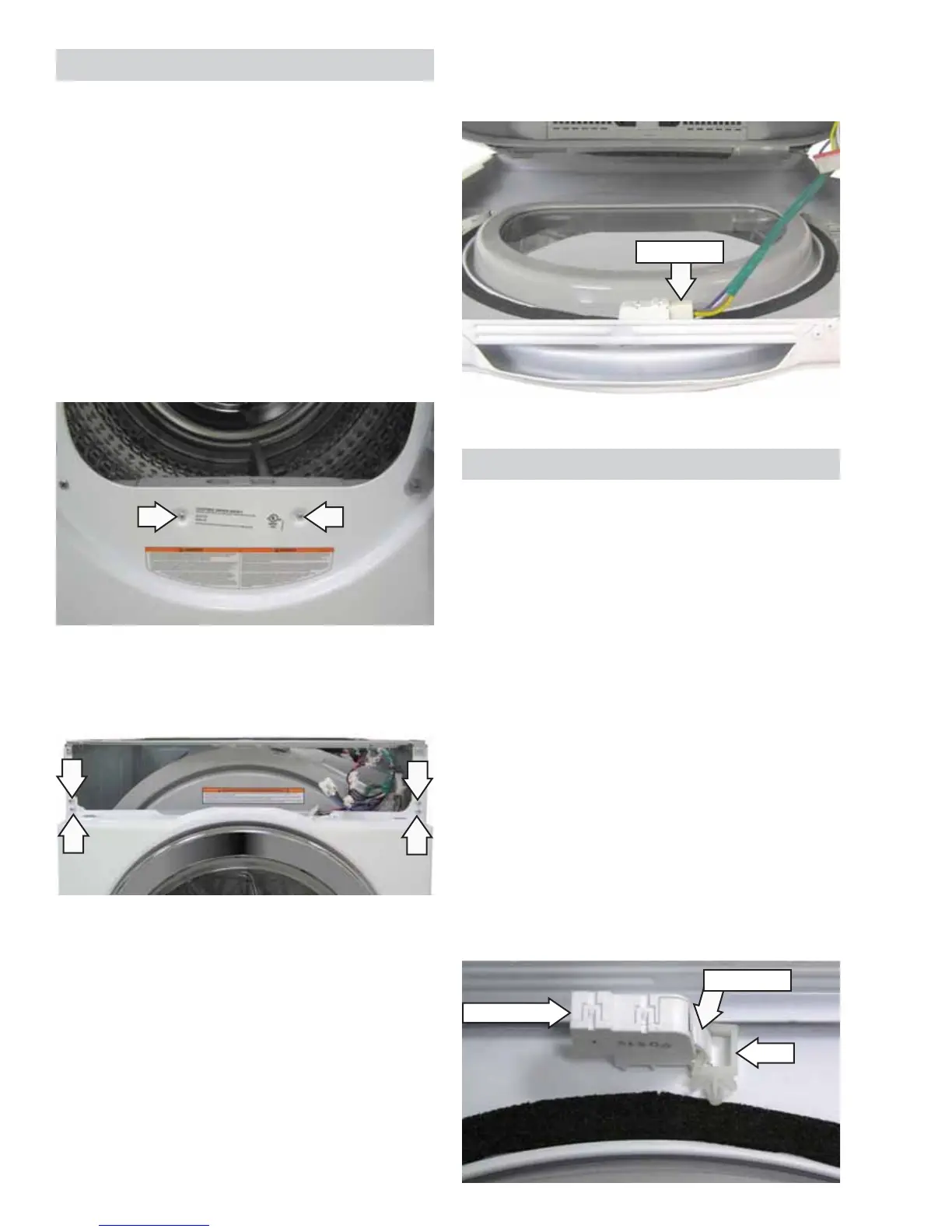
Open the door, then remove the 2 Phillips-head 3.
screws located in front of the lint fi lter.
4. Close the door, then remove the 4 Phillips-head
screws from the top corners of the front panel.
5. Pull the top of the front panel away from the
cabinet, then disconnect the door switch wire
harness.
6. Lift the front panel off of the cabinet.
Disconnect
Door Switch
The door switch is fastened to the front panel by
2 locking tabs. When the dryer door is closed, the
switch will complete the motor circuit, allowing
dryer operation. When the door is open, the switch
will open the motor circuit, interrupting dryer
operation.
Operation of the door switch can be checked by
using the service test mode. (See Service Mode.)
Specifi c failures associated with the door switch can
initiate error code dE. (See Error Codes.)
To remove the door switch:
Pull the top of the drum support away from the 1.
cabinet, then disconnect the door switch wire
harness. (See Front Panel.)
Remove the clip from the locking tab.2.
Note: The clip on the locking tab of the door switch
is for manufacturing purposes only and does not
need to be replaced when replacing the door switch.
Clip
Door Switch
Locking Tab
(Continued Next Page)
 Loading...