November 2005
4-2 The Optional Display/User Interface (Option G)
Description of the
DewPro MMY30
Programming Matrix
In the DewPro trace moisture transmitter with display option, a
matrix-style input is used for programming the unit of measure,
measuring range, error status of output, and output adjustment. Each
option is assigned coordinates on the 10 by 10 matrix, specified with
V (vertical), H (horizontal) and a number for each. You select the
desired option by entering the matrix position.The following sections
describe the features and usage of the various matrix locations as they
apply to the MMY30.
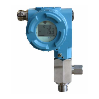
Figure 4-2: The MMY30 Optional Display
The display of the DewPro MMY30 continuously shows the current
matrix location using the vertical (V) and horizontal (H) coordinates
to designate the row and column, respectively. The bar graph
represents the output current in an analog fashion (refer to Figure 4-2
above). See Appendix A for an enlarged overview of the matrix with
all possible options, shown in Table 4-1 below.
Table 4-1: Matrix Input for Programming
MMY30 H0 H1 H2 H3 H4 H5 H6 H7 H8 H9
V0
Display Moisture
Va lu e
Select
Devices Unit
0=°C
1=°F
35=ppm
v
Loop #1
at Fault
0=-10%
1=110%
2=Hold
V1
Dewpoint
°C 4 mA
Dewpoint
°C 20 mA
ppm
v
20 mA
V2
V3
Pressure ppm
v
Constant (bar)
Output
D/A Cal 4 mA
Output
D/A Cal 20 mA
V4
V5
V6
V7
V8
Input Locking
50 = Unlock
V9
Current Error
Code
Previous
Error Code
Device ID Software
Ve rs io n
Set to Default
Va lu es
50 = Set Default
Reset Device
50 = Reset After
Calibration

 Loading...