Do you have a question about the GE AquaTrans AT868 and is the answer not in the manual?
Overview of the installation process and key topics covered.
Procedure for safely removing unit components from shipping containers.
Guidelines for selecting appropriate locations for the electronics enclosure and flowcell.
Guidance on choosing a suitable site for mounting the electronics enclosure.
Recommendations for ideal placement of the flowcell within the pipeline.
Adherence to guidelines for optimal transducer placement and alignment.
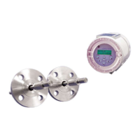
Detailed instructions for mounting the flowcell onto the pipeline.
Steps for securely mounting the electronics enclosure.
Instructions for establishing all necessary electrical connections to the flow transmitter.
Procedure for correctly connecting the unit to the power supply.
Step-by-step guide for connecting the upstream and downstream transducers.
Instructions for connecting the standard 0/4-20 mA analog output signals.
Guidance on connecting the meter's serial port for communication.
Overview of the AT868's user program and programming methods.
Procedure to enable or disable the flow measurement channel/path.
Configuration of system parameters for individual channels/paths.
Input of transducer type, pipe material, and dimensions for accurate measurement.
Setting a threshold to force zero display reading at minimal flow rates.
Configuration of signal limits, response times, and advanced features.
Accessing advanced meter features like KV/SS, MULTK, MASS, and CODEL.
Configuration of global system parameters, including units and messages.
Configuration of meter's inputs, outputs, and error handling responses.
Configuration of analog and totalizer/frequency output parameters.
Setting up the serial port parameters for PC communication.
Overview of the Liquid Crystal Display (LCD) features and adjustments.
Procedure to adjust the LCD contrast and backlight for optimal viewing.
Instructions to configure which data parameters are displayed on the screen.
Methods for resetting the meter's totalizer values using keypad, software, or switch.
Functionality to pause and restart measurements using the software.
Overview of calibrating and testing analog and totalizer/frequency outputs.
Procedure to calibrate zero-point and full-scale values for analog output signals.
Steps to set the 4 mA output point for the analog signal.
Steps to set the 20 mA output point for the analog signal.
Procedure to verify the accuracy of the analog output readings at various scales.
Procedure for testing the totalizer and frequency output signals.
Overview of the built-in error code message system for troubleshooting.
Indicates poor ultrasonic signal strength or signal exceeding programmed limits.
Occurs when calculated sound speed deviates from programmed values.
Indicates calculated velocity exceeds programmed range limits.
Signal quality falls below programmed correlation peak limit.
Signal amplitude exceeds programmed discriminator limits.
Acceleration exceeds limits due to poor flow or transducer alignment.
Explains troubleshooting procedures for electronics, flowcell, and transducers.
Accessing built-in parameters to aid in troubleshooting flowcell, transducer, or electrical issues.
Procedure to determine fluid sound speed and enter it into the meter.
Troubleshooting categories related to flowcell issues, including fluid and pipe problems.
Identifies common pipe-related issues affecting flow measurement accuracy.
Addresses issues related to transducer physical damage, coupling, and alignment.
Overview of on-site upgrades and parts replacement procedures.
Instructions for field-replaceable assembly of the LCD display and keypad.
Step-by-step guide for replacing the unit's fuse.
Procedure for replacing the EPROM chip storing the unit's software.
Overview of the AT868 flow transmitter's general operational characteristics.
Details on power supply, consumption, operating mode, and communication interfaces.
Information on digital display, communications, analog, and pulse outputs.
Technical details for wetted and clamp-on transducers, including materials and frequency.
Specifications for pipe dimensions and materials compatible with transducers.
Diagram illustrating the navigation path for channel-specific programming menus.
Diagram illustrating the navigation path for global programming menus.
Diagram illustrating the navigation path for channel setup menus.
Overview of CE Mark compliance requirements for EEC countries.
Requirements and modifications for ensuring electromagnetic compatibility.
Requirements for the Low Voltage Directive, including external power disconnect.
Section for recording specific site data entered via the User Program.
Procedure to determine path length (P) and axial dimension (L) for wetted transducers.
Guidelines for recording service details in the provided record table.
Table for recording diagnostic parameter values for troubleshooting.
Overview of the PanaView™ graphical interface for GE flowmeters.
Detailed steps for connecting the meter to a PC or printer via RS232.
Procedure to establish and configure communication settings in PanaView™.
Steps to add a meter to the configured communications port in PanaView™.
Functionality to modify meter settings like clock, signals, and totalizers via software.
Remote programming of operating parameters and file management via software.
Methods to reset the meter's time and date using software.
Procedure to read and display transducer signal data using PanaView™.
Action to clear the meter's totalizer values using the software.
Operations for managing site files, including saving and clearing.
| Type | Ultrasonic flow transmitter |
|---|---|
| Accuracy | ±1% of reading |
| Housing Material | Polycarbonate |
| Enclosure Rating | IP66 |
| Flow Velocity Range | 0.01 to 40 ft/s |
| Fluid Types | Liquids |
| Operating Temperature | -40°C to +60°C |
| Power Supply | 24 VDC |
| Outputs | 4-20 mA |
| Communication | Modbus |
| Enclosure | NEMA 4X |
| Pipe Size Range | 0.5 to 300 inches (15 to 7600 mm) |
| Temperature Range | -40 to 212°F (-40 to 100°C) |