Do you have a question about the GE XMTC and is the answer not in the manual?
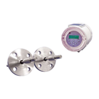
Key characteristics and design elements of the XMTC transmitter.
Explanation of how the XMTC measures gas concentration via thermal conductivity.
Step-by-step guide for physically mounting the XMTC transmitter unit.
Connecting the XMTC transmitter's electrical components and wiring.
Procedures for proper grounding of the XMTC enclosure for safety.
Step-by-step instructions for making signal wiring connections.
Procedures for establishing sample gas flow and ensuring proper operation.
Using the GE Instrument Data Manager software for configuration.
Procedures for performing field calibration of the XMTC.
Steps to execute zero and span calibrations.
Settings for calibration type and parameters.
Selecting the method for field calibration (1-point or 2-point).
Configuring the analog output signal for external devices.
Setting the percentage range for the 4-20 mA output.
Calibrating the 4 mA and 20 mA output signals.
Testing the 4-20 mA output at specified percentages.
Testing the percentage readings of the gas concentration.
Enabling or disabling error handling for specific conditions.
Configuring error handling for total drift.
Configuring error handling for drift/calibration errors.
Handling errors for gas signal mV range deviations.
Handling errors for gas percentage range deviations.
Accessing and configuring advanced system settings.
Technical performance metrics including accuracy, linearity, and stability.
Functional characteristics such as output, power, and temperature ratings.
Overview of the requirements and guidelines for CE marking compliance.
Detailed wiring instructions for weatherproof installations.
Detailed wiring instructions for explosion-proof installations.
Configuration of the XMTC cell's heater settings.
| Brand | GE |
|---|---|
| Model | XMTC |
| Category | Transmitter |
| Language | English |