XMTC User’s Manual 17
Chapter 2. Installation
2.5 Connecting to Other Components
This section gives interconnection details for using other GE devices in conjunction with your XMTC.
2.5.1 PS5R-C24 Power Supply
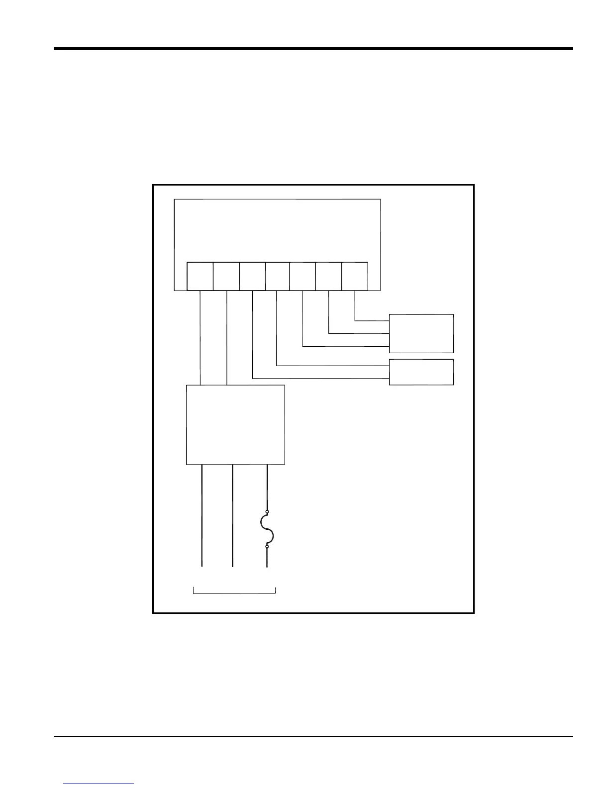
The GE 24-Volt power supply converts 100/120/220/240 VAC to 24 VDC for use with the XMTC. Figure 9 below
shows an interconnection diagram for the XMTC and the PS5R-C24 power supply.
Figure 9: Interconnection Diagram
Line
AC2
Neut
AC1
PS5R-C24
24 Volt
Power Supply
+24
VDC
GND
GND
GND
Neut
AC1
Line
AC2
AC Input
XMTC Transmitter
Red
Output
Device
Green
White
Black
TB1-1
+Vin
Black
TB1-2
RTN
White
TB1-3
4-20+
Green
TB1-4
4-20-
Red
TB2-1
RX
White
TB2-2
TX
Green
TB2-3
GND
RS232
Terminal
or PC