Chapter 2. Installation
16 XMTC User’s Manual
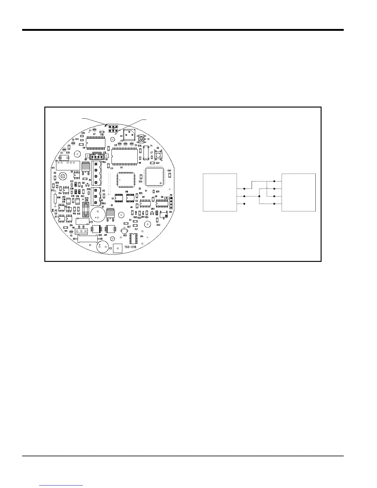
2.4.4 Wiring the Signal Connections (cont.)
7. Connect the RS485 serial port leads.
a. Locate the jumpers J7 and J8 on the main PCB, using Figure 8 below as a guide. Move the jumpers from
the left (RS232) side to the right (RS485) side.
b. Connect the other end of the cable to the RS485 converter, as shown in Figure 8 below.
Figure 8: Jumper Locations and RS485 Connections
8. Carefully plug the TB1 and TB2 connectors back onto the PCB, and reinstall the cover on the XMTC.
9. Connect the other ends of the cables to the 24 VDC power supply, the 4-20 mA input of the display device, and
the serial port of the computer or terminal (see the instruction manuals for those devices for details).
Jumper J7
Jumper J8
RX 1
TX 2
GND 3
1 TD OUT
2
3
4 RD IN
XMTC (TB2) RS485 Converter
Red
White
Green