9
8 7
6
5
4 3
2
1
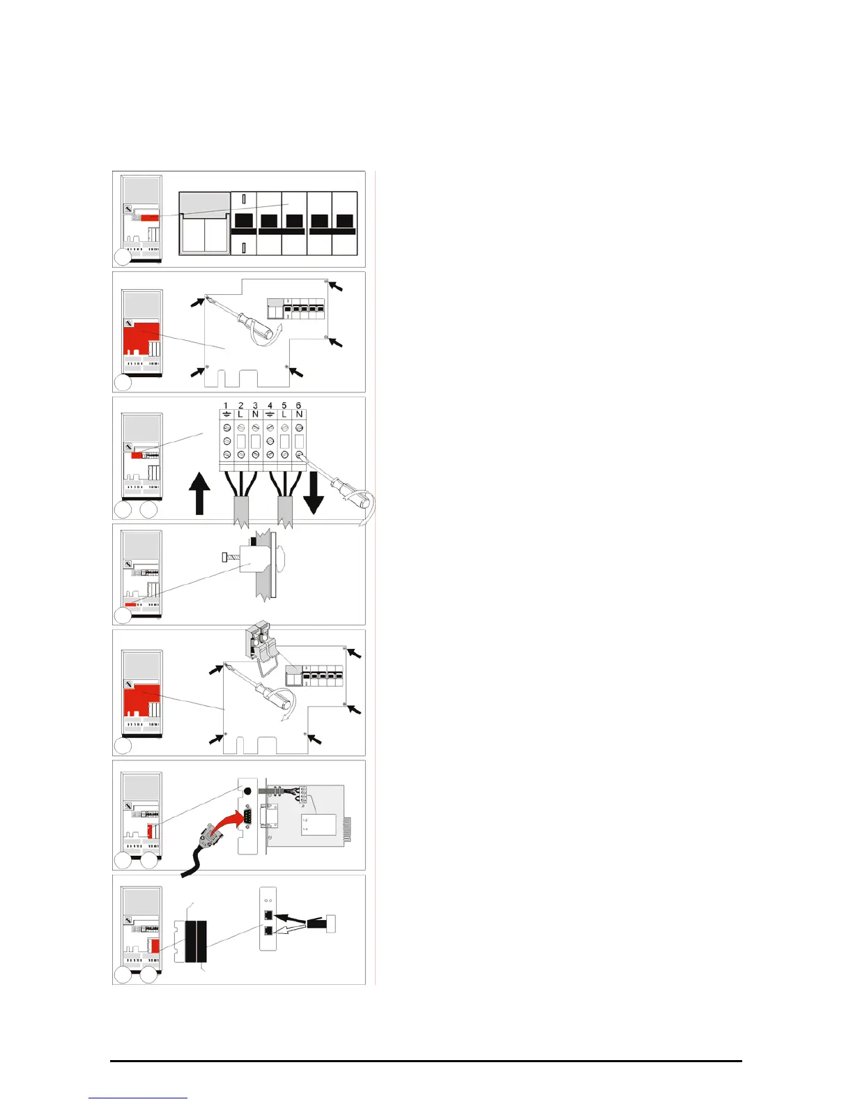
1. Make sure that all circuit breakers (7-8-9) are in ‘off’
position (down).
2. Loosen the 5 screws and remove the metal plate (11)
that covers the I/O terminals.
3. Input (11a). Connect the mains supply wires to the
terminals 2 (Line) and 3 (Neutral) and the ground wire
to terminal 1. Ground connection is essential!
4. Output (11b). Connect the load wires to the terminals
5 (Line) and 6 (Neutral) and the ground wire to
terminal 4. Ground connection is essential!
5. Use the clamps that came with the unit to attach the
wires to the rear of the cabinet. Position the clamps in
the slots (16).
6. Re-install the metal cover plate (11). Insert the 2
battery fuses in the fuse holder (17) and close the
fuse holder.
7. An emergency shutdown switch can be connected to
connector J3 on the RS232/Contact Interface Card,
between pins 3 and 4. See section 6.2 for more
information.
8. For advanced communication possibilities, the
RS232/contact interface port (12a) can be connected
to a computer system. See section 6.1 for more
information.*
9. The middle ‘option slot’ (13) allows easy installation of
plug-in cards: SNMP Card or Relay Card. See
sections 6.3 and 6.4 for more information.*
10. The right ‘option slot’ (14) allows easy installation of
the RPA-card (Redundant Parallel Architecture). If the
card is already mounted, and if the unit is intended to
be used stand-alone, a bus terminator (delivered with
the unit) has to be placed in one of the two bus
connectors on the card. If the unit will be part of a
parallel system, see sections 4.5.5 and 7.3 for more
information.*
* The data cables can be attached to the cabinet with
tie-wraps, position the tie-wraps in the small holes
(18) underneath the option slots.
11. Connect the utility power to the UPS.
12. For a quick start proceed with section 5.2 ‘Start-up’.
Figure 8. LP 8/10

 Loading...


