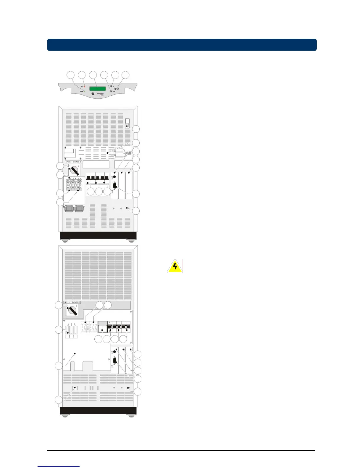
4 3 2 1 5 6
2x16 characters, shows UPS system data, status
messages, settings.
The language is selectable: English, German, French,
Italian, Spanish. Section 5.3.4 describes the selection
procedure.
2-4 Push-buttons
With the button keypads ‘Down’ (2) and ‘Up’ (4) you can
scroll through the several screens, with keypad 'Enter/Reset'
(3) a selection is confirmed. Keypad activity is accompanied
by a short beep. If there is no keypad activity during 20
seconds the LCD screen will return to the default screen
(except for the service screens, see section 5.3.3).
5 LED 'operation' indicates normal operation.
6 LED ‘alarm’, indicates an alarm situation, accompanied by
alarm message(s) on the display and a sounding buzzer.
See section 5.3.2 for more information.
7 Switch ‘UPS on/off’, turns on/off the complete UPS, including
the bypass!
8 MCB ‘Mains on/off’, protection fuse for mains input and
battery charger.
9 MCB ‘Bypass on/off’, fuse to protect the system in case of
severe overload or short circuit in the UPS load.
10 Manual Bypass Switch: 1 = Load on UPS
2 = Load on mains
CAUTION: In position 2, if the input line is
energized, the output is also live regardless the
position of the MCBs ‘mains’ and ‘bypass’.
11 Cover of the I/O terminals, behind it:
11A Input terminals
1 = Ground, 2 = Line, 3 = Neutral
11B Output terminals
3/5/6kVA: 4 = Line, 5 = Neutral, 6 = Ground
8/10kVA: 4 = Ground, 5 = Line, 6 = Neutral
12 RS232/Contact Interface Card, with:
12a - RS232 Interface Port (see section 6.1)
- Emergency shutdown (see 4.5.1 / 4.5.3 and 6.2)
- Battery disconnected, pin 1-2 (can be used for
external signalling).
13 Free option slot for plug-in cards:
- Relay Card (see 6.3)
- SNMP Card (see 6.4)
14 Option slot for RPA Card (Redundant Parallel Architecture).
See 4.5.5 and 7.3.
15 DC socket / connector.
16 Slots to fasten cable clamps.
17 Battery fuse holder.
Figure 12. Front and rear panel
top: LP 3/5/6-11
bottom: LP 8/10-11
18 Holes to fasten data cables.
OPM_LPE_11X_3K0_10K_1GB_V041 16 GE DE LP 11 UPS: User manual 4.1 (GB)

 Loading...


