46
06 Electrical Connection
User Manual V1.0-2023-10-30
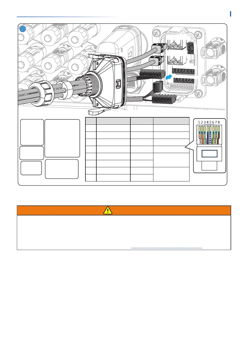
DRED/RCR:
11: COM/DRM0 or
REF_1
12: REFGEN or
REF_2
13: DRM 4/8 or DI_4
14: DRM 3/7 or DI_3
15: DRM 2/6 or DI_2
16: DRM 1/5 or DI_1
Dry Contact
1: DO1-
2. NC
3: DO1+
9: DO2-
10: DO2+
Power Supply
4: GND
5: 12V_S
RSD Control
5: 12V_S
6: RSD_12V
Remote Shutdown
7: GND
8: Remote Shutdown
PIN Color EMS/PAR Denition
1 Orange and White 485A3 -
2 Orange 485B3 -
3 Green and White NC -
4 Blue GND signal ground wire
5 Blue and White CAN_L
CAN bus
6 Green CAN_H
7 Brown and White SYN_BUS1
Parallel syn signal
8 Brown SYN_BUS2
1
4
5
1
2
3
11 12 13 14 15 16
4 5 6 7 8 9 10
11 12 13 14 15 16
1
2
3
4 5 6 7 89 10
EMS/PAR
EMS/PAR
6�7�2 Connecting the BMS or Meter Communication Cable
WARNING
• For GEH15-3U-10 and GEH20-3U-10, please connect the cable to BMS1 port to realize BMS
communication. Otherwise, BMS communication may fail.
• For GEH25-3U-10, GEH29.9-3U-10, and GEH30-3U-10, please connect the cable to BMS1
port to realize BMS communication when single battery system is connected. Otherwise, BMS
communication may fail. For more details, refer to 6.5 Connecting the Battery Cable.