3.3.8 Rear panel
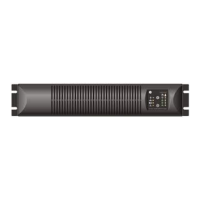
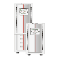
Rear Panel 5/6 kVA:
1. Input / output terminals
(see section 3.3.9)
2. External battery connector
3. Output breaker:
2pole, 30A/250Vac
4. Fans
5. SNMP card slot
6. DB9 communication port
7. Additional ground connector
8. REPO contacts
(see section 4.4.10)
9. Input breaker: 2pole, 30A/250Vac
10. Maintenance Bypass
(Optional Power Distribution Unit)
Unit with standard Power Distribution Unit:
fig. 3.3.8.a
Unit with Optional PDU (see section 6.6.1)
fig. 3.3.8.b
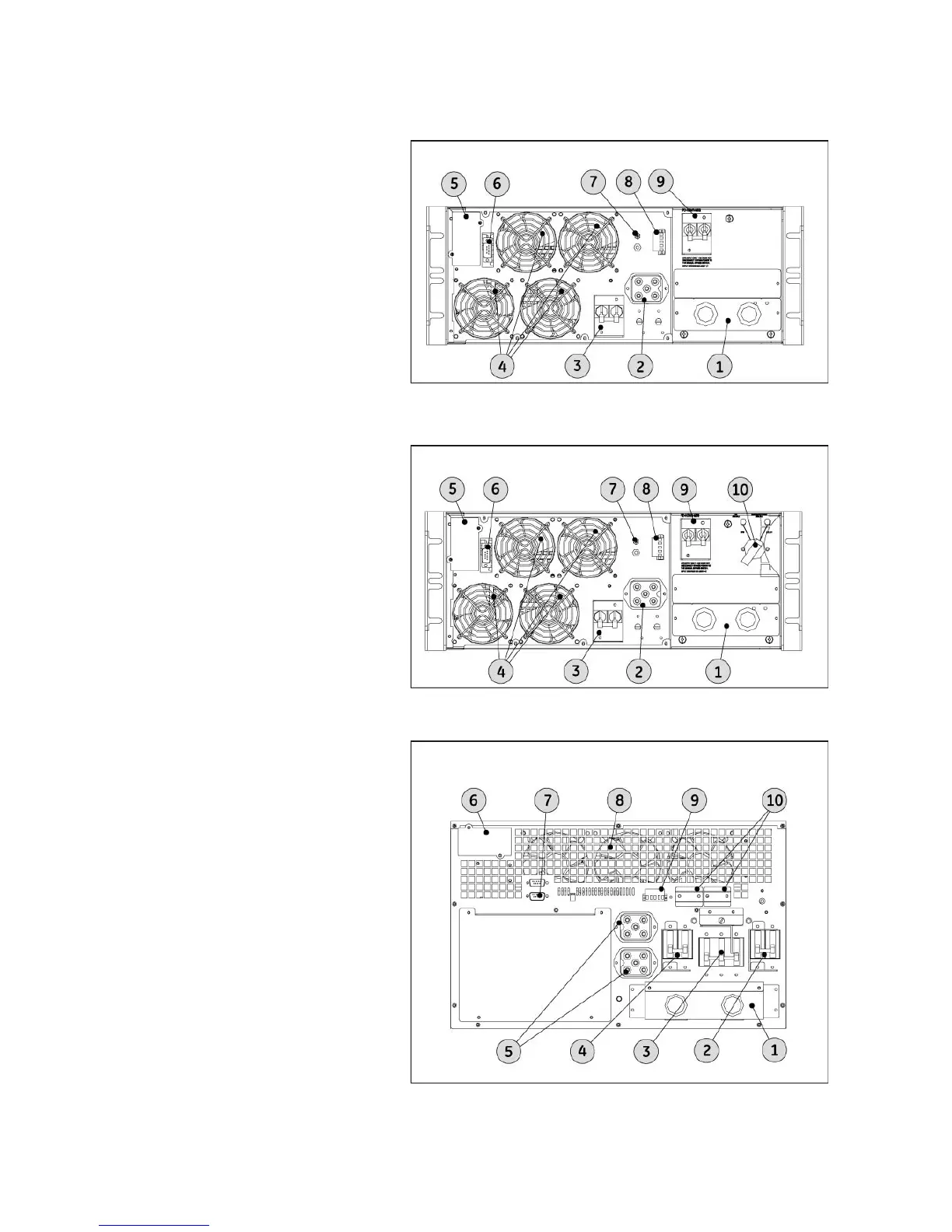
Rear Panel 8/10 kVA:
1. Input/Output terminals
(see section 3.3.9)
2. Input breaker: 2pole, 60A/250Vac
3. Maintenance Bypass
(see section 4.3.3)
4. Output breaker: 2pole,
60A/250Vac
5. External battery connectors
6. SNMP card slot
7. DB9 Communication port
8. Fan Module
9. REPO Contacts
(see section 4.4.10)
10. Parallel ports (see section 3.4.2)
fig. 3.3.8.c
5/6 kVA
5/6 kVA
8/10 kVA
modifications reserved 17 User manual GT Series 5/6/8/10 kVA UPS 1.0 (US)

 Loading...