4 OPERATION
4.1 OPERATING PANEL
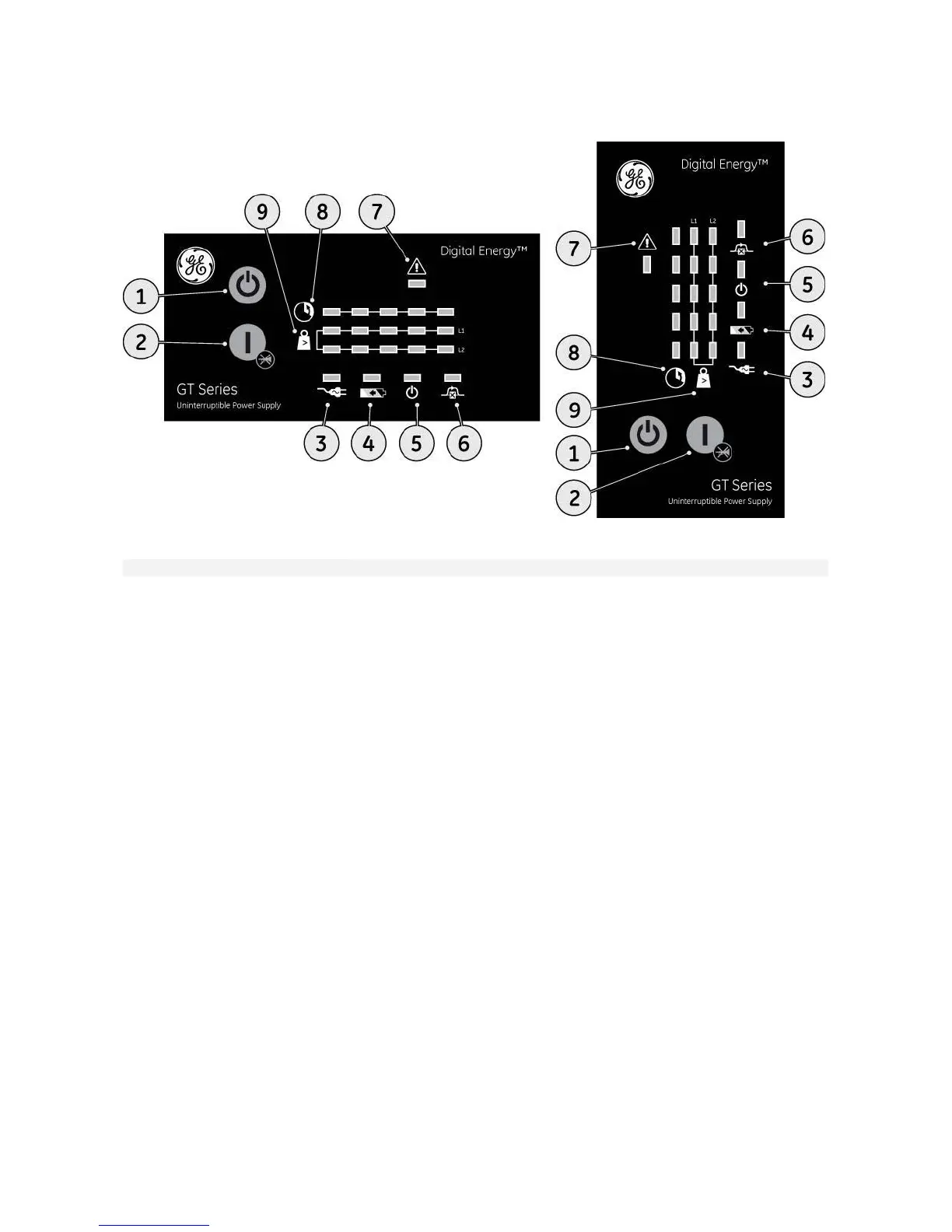
fig. 4.1: operating panel
switch / LED main function
1
‘UPS off’ switch switches the UPS from normal operation to bypass and from bypass or
battery to standby.
2
‘UPS on’ switch switches on the UPS, starts quick battery test (see section 4.5), mute the
buzzer.
3
LED ‘mains available’ (green) indicates availability of power mains.
4
LED ‘battery’ (yellow) on in case of battery operation: the mains power fails, and the internal
batteries supply the required power until either they are depleted or mains
power returns.
5
LED ‘operation’ (green) on when the output is supplied by the UPS (inverter).
6
LED ‘bypass’ (yellow) on when the UPS operates in bypass mode: the incoming mains power is
channeled directly to the load. Blinks if the input voltage is out of bypass
tolerance (see section 4.4.4 for more details).
7
LED ‘alarm’ (red) on in case of alarm.
8
LED bar ‘runtime capacity’
the remaining available battery runtime for the actual load, in % of the
maximum runtime with the actual load. When the alarm LED is on, this bar
may show a combination of LEDs, describing the Alarm cause (see 4.4).
1º LED: 0-20% green
2º LED: 21-40% green
3º LED: 41-60% green
4º LED: 61-80% green
5º LED: 81-100% green
9
LED bars ‘load’
indicates to what extent the output capacity of the UPS is used by the
actual load for each output line (L1 and L2). If e.g. the 25%, 50% and 75%
LED are on for Line 1 and the 25% and 50% LED are on for Line 2, the load
exceeds 50% of the maximum load for Line 1 and 25% for Line 2. If all 5
LEDs are on the unit operates in overload. As this is an abnormal situation
the alarm LED will be on as well.
1º LED: 0-25% green
2º LED: 26-50% green
3º LED: 51-75% green
4º LED: 76-100% green
5º LED: >100% yellow
modifications reserved 22 User manual GT Series 5/6/8/10 kVA UPS 1.0 (US)

 Loading...