3.4.2 Installing the parallel connection
NOTE
Ensure that the UPS is isolated prior to installation; no live input source may be
connected to the UPS during the installation procedure. Open all the input/output
switches/breakers on the power distribution and ensure no one is able to close
them during this installation step.
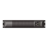
1. Localize the parallel port on the rear side
of the unit (fig. 3.4.2.a)
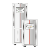
2. Connect the DB 15 parallel cable provided
with the UPS to the parallel port (fig.
3.4.2.b) and tighten it.
3. One cable connects two UPS in parallel.
To connect a third UPS into the parallel
system, repeat the process as above
(fig. 3.4.2.d)
4. For a quick start of the system proceed
with section 4.2.3
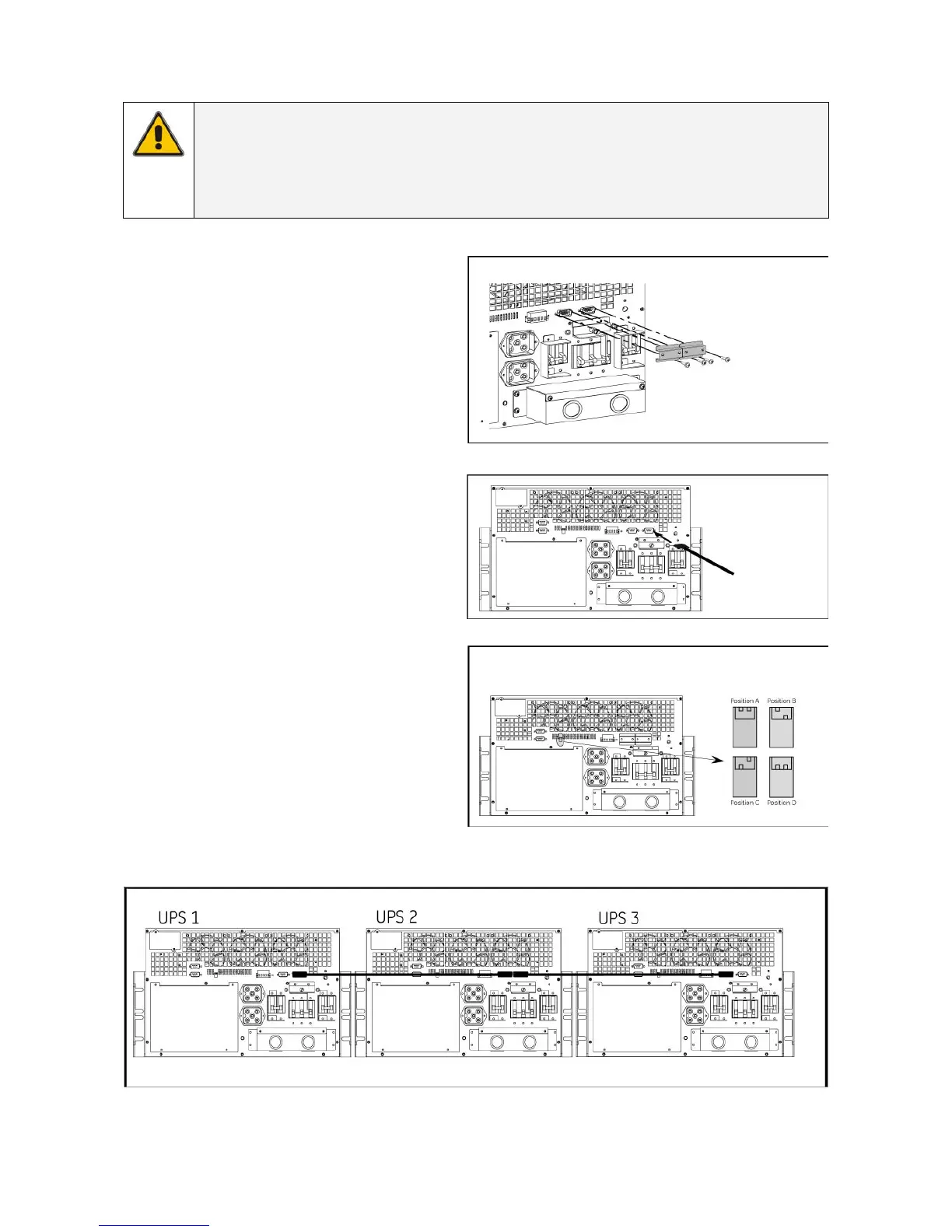
5. Each UPS needs a different configuration
of the DIPswitch as identification of unit
in the parallel system (fig. 3.4.2.c).
fig. 3.4.2.a
fig. 3.4.2.b
fig. 3.4.2.c
8/10 kVA
8/10 kVA
8/10 kVA
8/10 kVA
fig. 3.4.2.d
modifications reserved 21 User manual GT Series 5/6/8/10 kVA UPS 1.0 (US)

 Loading...