4.2.2 Start-up of a 8/10 kVA
1. Ensure that all breakers on the unit are
off.
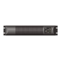
2. In case of external batteries are used
(see section 3.3.6 for battery
connection), switch on the battery
cabinet circuit breaker (fig.4.2.2.a).
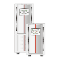
3. Ensure that Bypass circuit breaker
(see section 3.3.7) is on “UPS” position
(fig.4.2.2.b) or that protection bar is still
mounted.
4. Close all switches and breakers
upstream to the UPS.
5. Switch the input circuit breaker placed
on the rear side of the unit to position
“On” (fig.4.2.1.d). The “Mains available”
LED on the operating panel
(see section 4.1) is lighted on.
6. Wait 45 seconds to allow the output
voltage to stabilize.
7. Press keypad “UPS on” for 1 second.
Within few seconds “operation” LED will
be illuminated and “bypass” LED will be
extinguished.
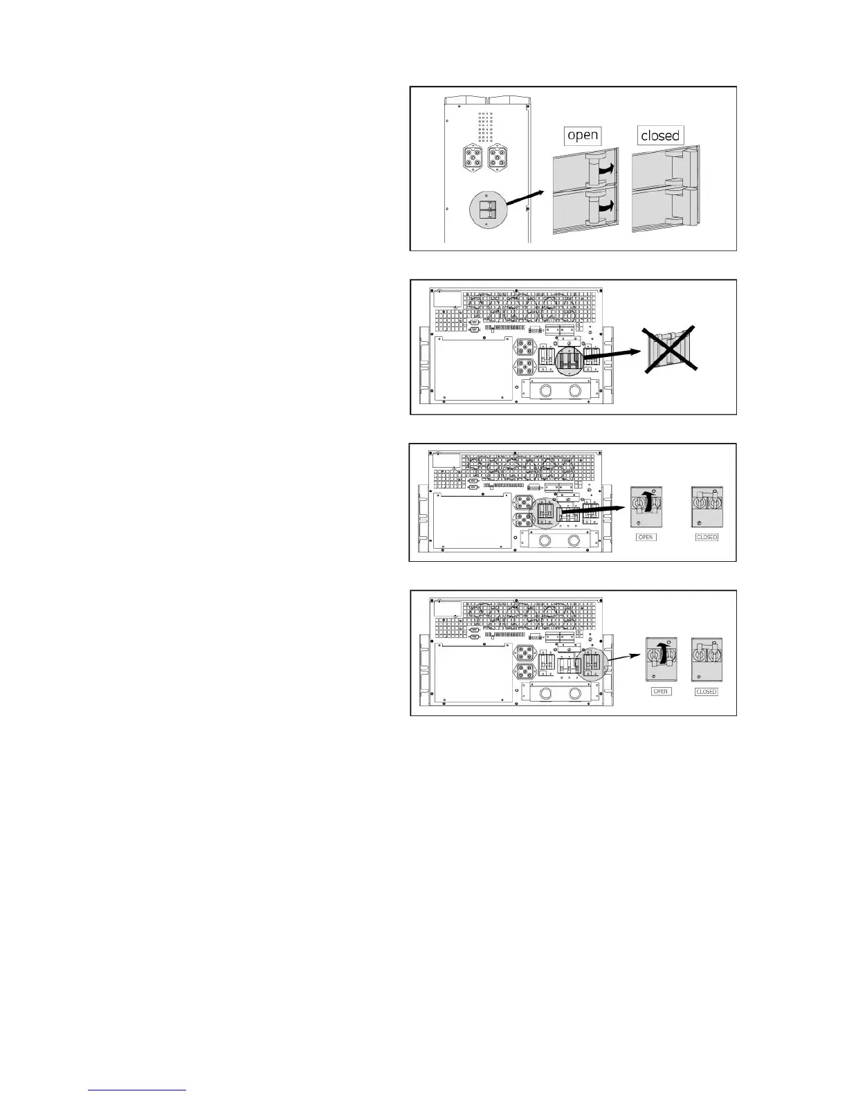
8. Close the Output circuit breaker placed
on the rear side of the unit (fig. 4.2.2.c).
9. The unit is now in operation; equipment
connected to the UPS can now be
switched on.
Load % will be shown on “load” LED bar.
fig. 4.2.2.a
fig. 4.2.2.b
fig. 4.2.2.c
fig. 4.2.2.d
8/10 kVA
8/10 kVA
8/10 kVA
8/10 kVA
4.2.3 Start-up of a parallel system (8/10 kVA models)
1. Ensure that all breakers on all the units of the system are off.
2. In case external batteries are used, switch on each circuit breaker (fig. 4.2.1.a / 4.2.2.a).
3. Ensure that all manual bypass switches are turned to “UPS” position (fig. 4.2.1.b / 4.2.2.b).
4. Close all switches and breakers upstream to all UPS of the system.
5. Switch to position “on” the output circuit breaker on all UPS in sequence (fig. 4.2.1.c / 4.2.2.c).
6. Switch to position “On” the input circuit breaker on all UPS in sequence (fig. 4.2.1.d / 4.2.2.d).
7. Wait 45 seconds to allow the output voltage to stabilize.
8. Press keypad “I” on each UPS for 1 second. Within few seconds LED ‘operation’ will be illuminated
and LED ‘bypass’ will be extinguished.
9. The parallel system is now in operation and the connected equipment can now be switched on.
The load will be shared between the UPS as shown on the LED bar ‘load’.
modifications reserved 24 User manual GT Series 5/6/8/10 kVA UPS 1.0 (US)

 Loading...