7.5 POWER UNIT MAINTENANCE
For maintenance purposes the power unit can be replaced while output is transferred to manual bypass
(for 5/6 kVA models only with PDUs including manual bypass switch). See following sections for detailed
description on replacement procedure.
WARNING
The UPS has to be switched to manual bypass before power unit replacement
otherwise output power is lost.
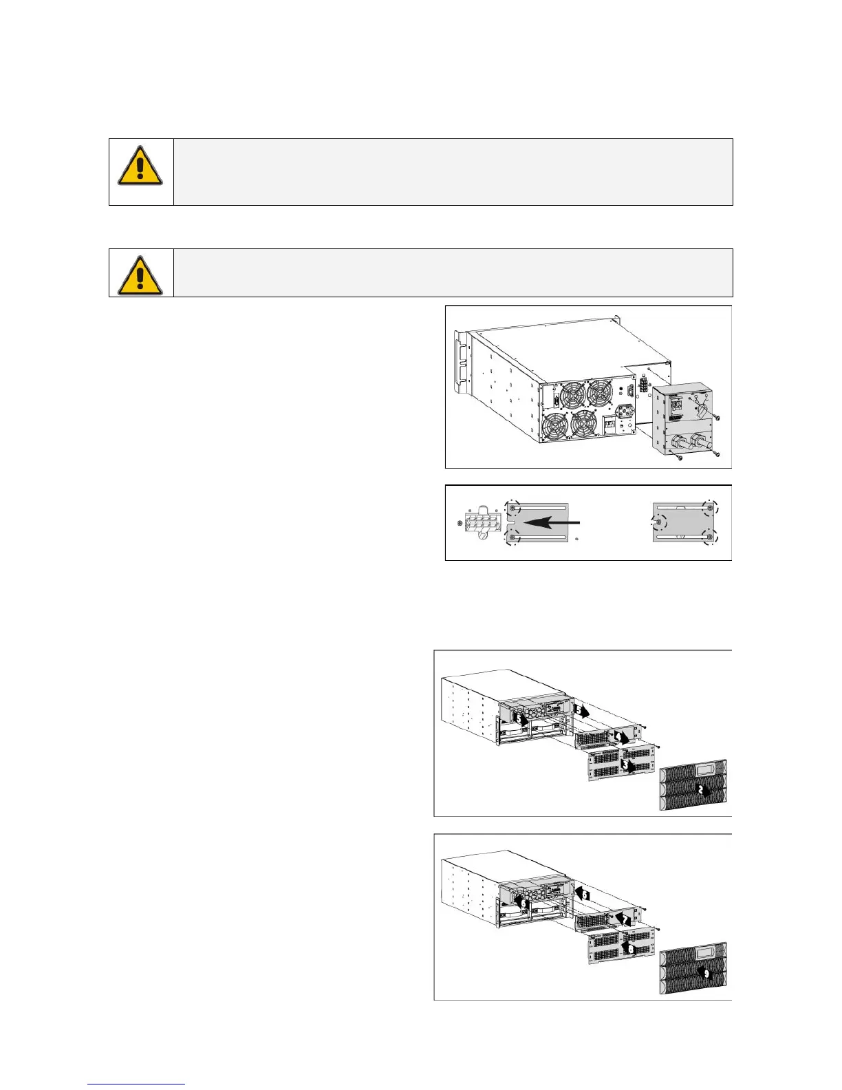
7.5.1 Power unit replacement (for 5/6 kVA models)
NOTE
UPS replacement is only possible with PDUs including manual bypass switch.
1. Switch the UPS to manual bypass;
see section 4.3.3 for further details.
2. Loosen the 3 mounting screws of the optional
PDU (fig. 7.5.1.a) and slide it out from the power
module.
3. Loosen the 2 terminal cover fixation screws, on
the back side of the optional PDU slide the
cover over the terminals and fix the screws
again (fig. 7.5.1.b)
4. Power module can now be replaced. If internal
batteries are not at end of life they can be
placed in the new power module
(see section 3.3.3)
5. Slide optional PDU into new power module and
fix the three mounting screws (fig. 7.5.1.a).
6. Switch the UPS back to normal operation;
see section 4.3.3 for further details.
fig. 7.5.1.a
fig. 7.5.1.b
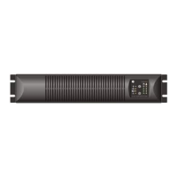
5/6 kVA
7.5.2 Power unit replacement (for 8/10 kVA models)
1. Switch the UPS to manual bypass; see
section 4.3.3 for further details.
2. Remove the 3 front covers (2, fig. 7.5.2.a).
3. Loosen the 3 mounting screws of the
internal battery cover and remove it
(3, fig. 7.5.2.a).
4. Loosen the 5 mounting screws of the power
module cover and remove it (4, fig. 7.5.2.a).
5. Slide the power module out of the box
(5, fig. 7.5.2.a).
6. Power module can now be replaced.
7. Slide in the new power module until the rear
connector of the power module is plugged
in the socket on the UPS (6, fig. 7.5.2.b).
8. Reposition the power module cover and fix it
with the 5 screws. In the same way mount
the internal battery cover (7 & 8, fig. 7.5.2.b).
9. Place again the 3 front covers (9, fig. 7.5.2.b).
10. Switch the UPS back to normal operation;
see section 4.3.3 for further details.
fig. 7.5.2.a
fig. 7.5.2.b
8/10 kVA
8/10 kVA
modifications reserved 39 User manual GT Series 5/6/8/10 kVA UPS 1.0 (US)

 Loading...