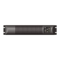
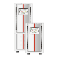
6. Re-install the terminal
cover (fig. 3.3.9.e).
7. In case of external
batteries, ensure the
battery cable is connected
between the battery
cabinet and the power unit.
(see 3.3.5 / 3.3.6).
8. Connect the utility power to
the UPS.
9. For a quick start proceed
with section 4.2.1.
If parallel-operating units will be
installed, please proceed with
section 3.4. Otherwise, proceed
with section 4.
fig. 3.3.9.f
fig. 3.3.9.g
5/6 kVA
8/10 kVA
NOTE
The UPS output sockets are live as soon as the UPS is connected to the mains,
even if the UPS has not been switched on via the front panel.
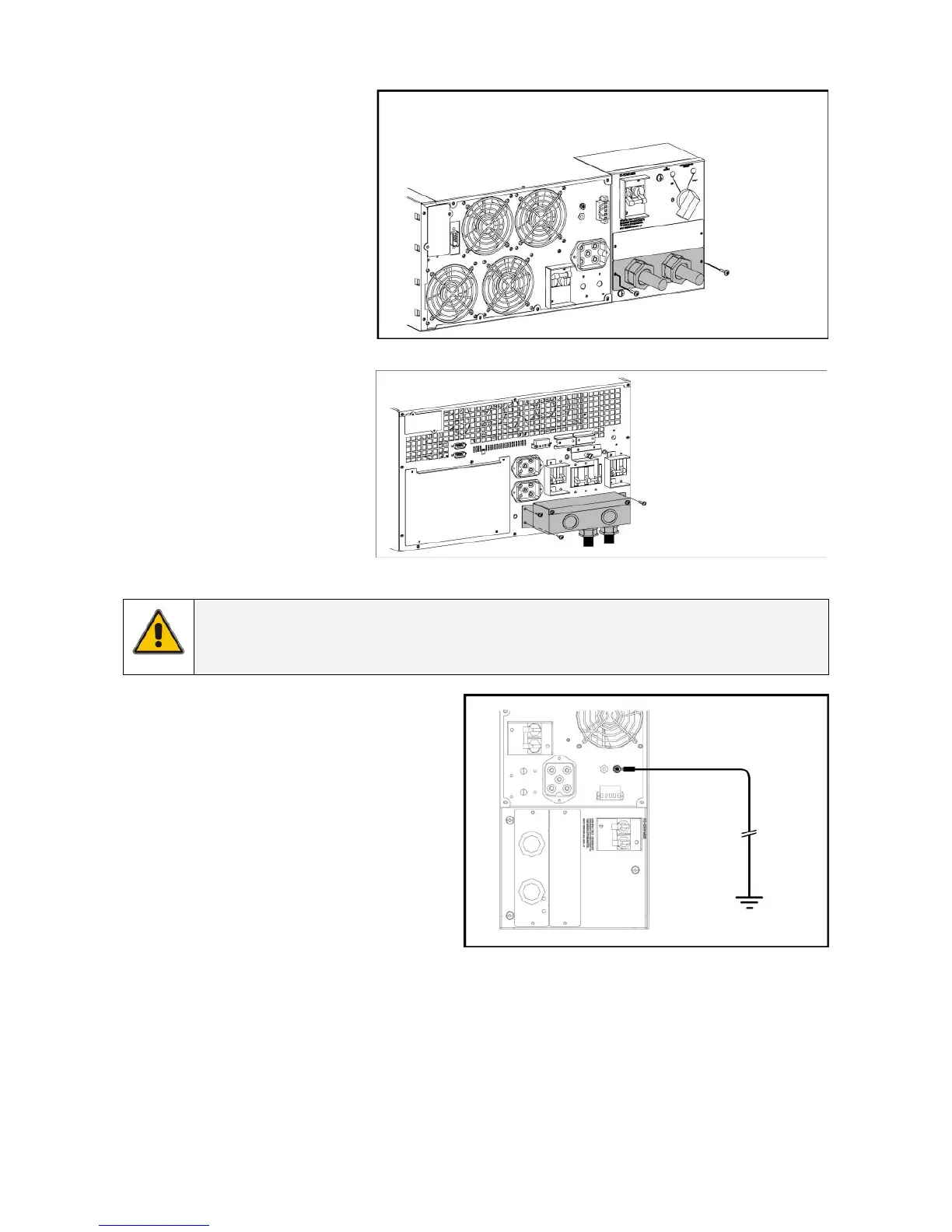
For 5/6 kVA models an additional
ground connection is required (main
ground can be removed with the PDU).
Connect the UPS case to the nearest
available ground connection with an
8 AWG (10 mm
2
) copper wire
(see fig. 3.3.9.h).
fig. 3.3.9.h
5/6 kVA
modifications reserved 19 User manual GT Series 5/6/8/10 kVA UPS 1.0 (US)

 Loading...