Operating Instructions Installation InstructionsTroubleshooting Tips
Consumer Support
Safety Instructions
8
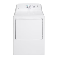
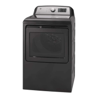
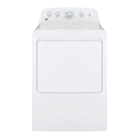
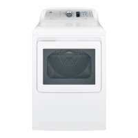
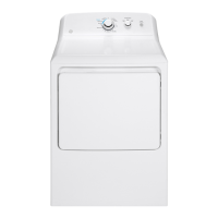
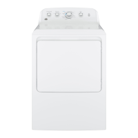
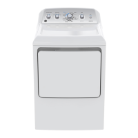
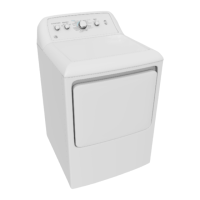
Electric Dryer
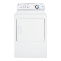
EXHAUST INFORMATION
THIS DRYER COMES READY FOR REAR
EXHAUSTING. IF SPACE IS LIMITED, USE THE
INSTRUCTIONS IN SECTION 9 TO EXHAUST
DIRECTLY FROM THE SIDES OR BOTTOM OF
THE CABINET.
EXHAUST CONNECTION
STANDARD REAR EXHAUST
9HQWHGDWÀRRUOHYHO
3 4
:$51,1*86(21/<0(7$/FPµ
DUCT. DO NOT USE DUCT LONGER THAN
SPECIFIED IN THE EXHAUST LENGTH TABLE.
WARNING - TO REDUCE THE RISK
OF FIRE OR PERSONAL INJURY:
Using exhaust longer than speci¿ed length will
Increase the drying times and the energy cost.
Reduce the dryer life.
Accumulate lint, creating a potential ¿re ha]ard.
The correct exhaust installation is YOUR RESPONSIBILITY.
Problems due to incorrect installation are not covered by
the warranty.
The 0AXI0U0 ALLOWABLE length of the exhaust system
depends upon the type of duct, numEer of turns, the type of
exhaust hood wall cap, and all conditions noted Eelow. Both
rigid and ÀexiEle metal duct are shown in the taEle Eelow.
This dryer must Ee exhausted to the outdoors.
Use only metal duct.
Do not terminate exhaust in a chimney, any gas
vent, under an enclosed Àoor crawl space, or into
an attic. The accumulated lint could create a ¿re
ha]ard.
Provide an access for inspection and cleaning of
the exhaust system, especially at turns. Inspect and
clean at least once a year.
Never terminate the exhaust into a common duct
with a kitchen exhaust. A comEination of lint and
grease could create a ¿re ha]ard.
Do not oEstruct incoming or exhausted air.
EXHAUST SYSTEM CHECKLIST
HOOD OR WALLCAP
Terminate in a manner to prevent Eack drafts or entry of Eirds or other
wildlife.
Termination should present minimal resistance to the exhaust air Àow
and should reTuire little or no maintenance to prevent clogging.
Never install a screen in or over the exhaust duct. This could cause lint
Euild up, thus creating a ¿re ha]ard.
Wall caps must Ee installed at least 3 cm 12 in. aEove ground level or
any other oEstruction with the opening pointed down.
If roof vents or louvered plenums are used, they must Ee eTuivalent to
a 1 cm 4 in. dampened wall cap in regard to resistance to air Àow,
prevention of Eack drafts, and maintenance reTuired to prevent clogging.
SEPARATION OF TURNS
For Eest performance, separate all turns Ey at least 1.2 m 4 ft. of straight
duct, including distance Eetween last turn and exhaust hood.
TURNS OTHER THAN 90º
One turn of 45 or less may Ee ignored.
Two 45 turns should Ee treated as one 9 turn.
Each turn over 45 should Ee treated as one 9 turn.
SEALING OF JOINTS
All Moints should Ee tight to avoid leaks. The male end of each section of
duct must point away from the dryer.
Do not assemEle the ductwork with fasteners that extend into the duct.
They will serve as a collection point for lint.
Duct Moints should Ee made air and moisture-tight Ey wrapping the
overlapped Moints with duct tape.
Hori]ontal runs should slope down toward the outdoors 1.2cm 1/2 in. /ft.
INSULATION
Duct work that runs through an unheated area or is near air conditioning
should Ee insulated to reduce condensation and lint Euild-up.
If using ÀexiEle metal duct, please refer to page 1.
NOTE WE STRONGLY RECO00END SOLID 0ETAL EXHAUST
DUCTING. HOWEVER, IF FLEXIBLE DUCTING IS USED IT MUST BE
0ETAL NOT PLASTIC.
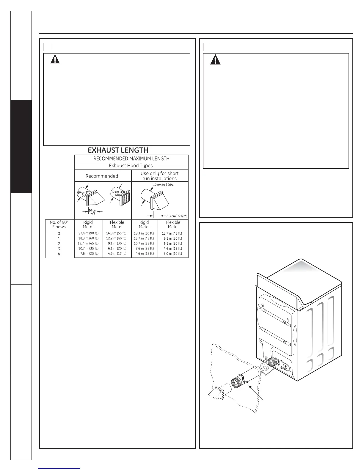
CUT THE 0ETAL EXHAUST DUCT
NOT SUPPLIED TO THE PROPER
LENGTH.
For straight
line installation,
connect the dryer
exhaust to the
external exhaust
hood using duct
tape or clamp.
 Loading...