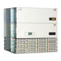
Do you have a question about the GE Infinity S and is the answer not in the manual?
| Brand | GE |
|---|---|
| Model | Infinity S |
| Category | Power Supply |
| Language | English |
Attach the system to the frame using twelve 12-24 screws. Torque to 35 in-lb.
Connect chassis ground lug using #10 or 1/4" on 5/8" centers. Minimum 10 AWG recommended.
Connect DC reference ground lug - 5/16" or 3/8" on 1" centers. Torque to 160 in-lb.
Connect 120/208/220VAC at rear of each rectifier shelf. Follow safety rules.
Shows DC circuit, battery connections to bus, and load connections via breakers.
Set jumpers 1-10 for alarm relays (Close/Open on Alarm). Factory default is Open.
Connect Pulsar Plus controller to J2, J3, J4, and J5 per site engineering.
Slide power unit into slot, open faceplate latch, slide unit fully, close faceplate.
Daisy chain probes to J2 to monitor temp/voltage. Bolt probe under negative terminal connector.
Factory set to Open On Alarm. J4 provides primary customer alarm outputs.
Default alarm descriptions can be changed. J4 is a 10-pin latching connector.
View/change parameters via display, craft port (EasyView2), or LAN port (web pages).
Display colors indicate status. Clear alarms via menu path: Control/Operation > Clear Events.
Overview of front panel display, navigation buttons, and menu access.
Configure LAN port to SERVER mode, access web pages at 192.168.2.1. Use default password 'Administrator'.
Displays Plant Status, Battery, and Plant Configuration. Change default password immediately.
Follow national/local rules, use proper connectors, torque, cable dress, breakers, fuses.
Connect chassis to ground, provide disconnects, alarm signals, and external current limiting.
Use insulated tools, remove metallic objects, follow LOTO, wear safety glasses, ESD strap.
Test circuits, identify hazards, avoid live circuits, be aware of medical device effects.
 Loading...