– 25 –
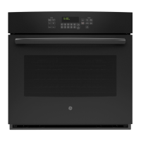
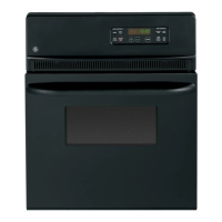
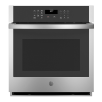
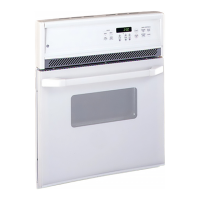
Control Panel (Double and Single Wall Ovens)
Removal and Replacement
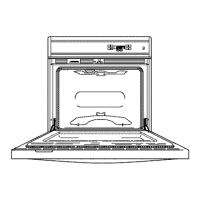
1. Remove the three
1
/
4-
in. hex head screws
securing the control panel to the vent trim.
Note: Screws are located under the control panel
and can be accessed by opening the oven door
and removing them from the bottom.
2. The panel has keyhole slots at the top and is
held very tight. Carefully push the panel up,
then pull out at the bottom.
Control Panel Insert (Slide-In Range)
Removal and Replacement
1. Remove the
Glass Touch Assembly.
2. Remove the four
1
/4-in. hex head screws
securing the metal control panel insert to the
control panel trim.
3. Disconnect the two wiring harnesses by
unplugging the 9-pin and 15-pin connector
blocks.
4. Disconnect the 4 connectors on the main
logic board (MLB).
Note: When reassembling, carefully position the
harness wires when reinserting the control panel
insert.
Glass Touch Assembly (Slide-In Range)
Removal and Replacement
1. Disconnect power to the range.
2. Remove all surface unit knobs.
3. Unscrew the four plastic crystal retainers on
the infinite switches by turning counter-
clockwise.
Note: The retainers should only be hand tightened
when reinstalling.
4. Lift the glass touch assembly 3 inches away
from the control panel and unplug the ribbon
cable from the assembly.
Note: The ribbon cable and connector are very
fragile. Take extra care when removing. When
reassembling, do not pinch the ribbon connector
between the glass and control trim.
Cooktop (Slide-In Range)
Removing and Replacement
1. Remove the Glass Touch Assembly.
2. Remove the
Control Panel Insert.
3. Remove the control panel trim by removing
the five
1
/4-in. hex head screws attached to the
front edge of the cooktop and the five
1
/4-in.
hex head screws at the bottom attached to the
vent trim.
4. Remove the two
1
/
4-
in. hex head screws
securing the cooktop to the body side
extensions (1 screw per side).
5. Slide the cooktop assembly forward and lift
the cooktop off.
Note: Take extra care with the harness when
reinstalling the cooktop.
The 4 heating elements come in 3 sizes:
• Two 6-in. 240V, 1500W
• One 9-in. 240V, 2500W (dual unit 6-in. and 9-
in.)
• One 8-in. 240V, 2000W
 Loading...