– 29 –
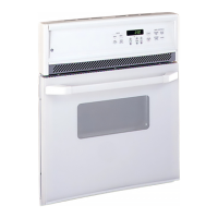
Main Power Board
K102
K11
K10
J3
J1
K8
K7
J4
J1 - Relay control inputs from Main Logic Board J3
J3 - DC power output and line monitor signals to
Main Logic Board J5
K11 - L2 Double Line Break Relay for upper oven
broil, bake, and bake 2 elements
K7 - Broil ON/OFF
Relay
K8 - Bake ON/OFF Relay
J4 - Output to 120 VAC loads (lamps/motors/fans)
K102 - L2 Double Line Break Relay for convection element
K10 - Convection Element ON/OFF Relay
K103 - Bake 2 ON/OFF Relay
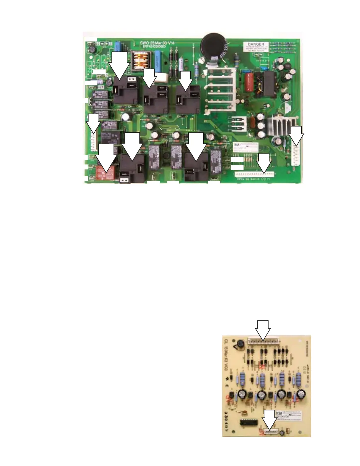
Current Limit Board (Slide-In Range Only)
J2 - L2 and power signals from surface unit
elements
J1 - 5 VDC power input and 4 surface unit
status signals output to J4 Main Logic
Board
The current limit board receives power signals from
the infinite switches and converts them to logic
signals so the main logic board can detect on/off
status.
K103
J2
J1
NO
NO
COM
NC
NO
NO
NO
COM
COM
COM
COM
J102
J101
J117
J114
J113
J112
J103
J108
J111 J107
J105
J109
Note: Although the board is
marked SWO, it is used in
all ovens.
 Loading...