CHAPTER 1: INTRODUCTION OVERVIEW
LM10 MOTOR PROTECTION SYSTEM – INSTRUCTION MANUAL 1–3
1.2.4 Power Supply
The LM10 Motor Protection System has an on-board power supply with a fuse that
converts the AC input to the levels necessary to operate this device. The operating range is
96 to 140 V AC, nominal 120 V control power (80% to 117%). The supply has
programmable auto-restart capability of up to 4 seconds. This also supplies necessary
power to the PDU at a TTL.
For correct measurement of power and power factor, the control power must be
connected across phase A and phase B of the three-phase power supply.
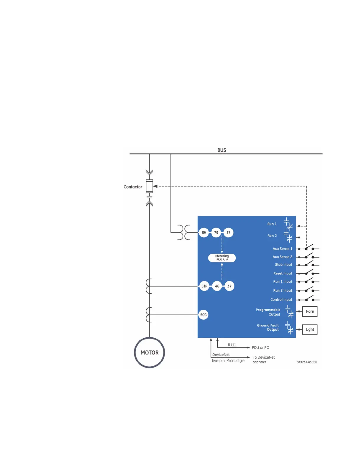
1.2.5 Block Diagram
A single line diagram for the LM10 Motor Protection System is shown below.
FIGURE 1–1: Functional Block Diagram