A–20 LM10 MOTOR PROTECTION SYSTEM – INSTRUCTION MANUAL
LM10 AND ALLEN-BRADLEY SLC500 VIA DEVICENET™ CHAPTER A:
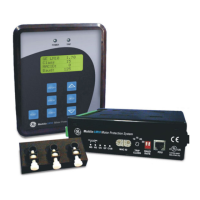
FIGURE A–7: Scanner Module Scanlist
Z Click on Scanlist tab.
The LM10 will be shown under Available Devices.
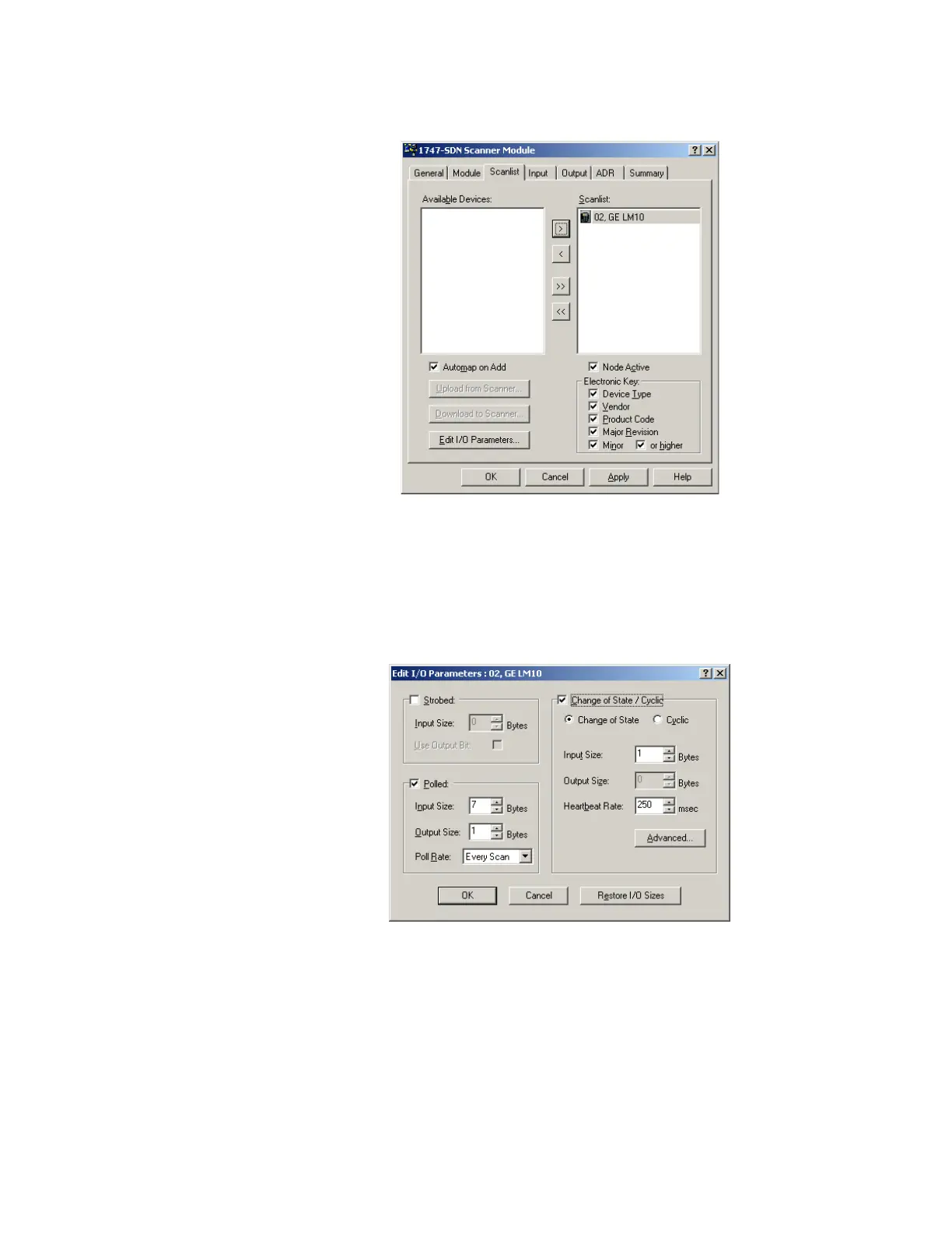
Z Click the right arrow to move under 'scanlist'. Double-click on
LM10-1 icon to edit the input/output parameters.
Z Select Polled and add 1 byte for the Input Size and Output Size.
After adding the input/output parameters, you will be prompted for
downloading to node 9
A.3.7 Control and Monitoring of the LM10
Polling I/O messaging is for control and monitoring of LM10 relay parameters.