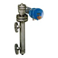
9.3. REMOVAL OF 12400 CASE AND TORQUE TUBE SUB-ASSEMBLY (SEE FIGURES 22 & 23)
a. Switch off power supply.
b. For instruments with a displacer chamber, close isolation valves, and purge the chamber.
c. Remove the upper flange (146) and blind flange (144).
d. Lower the torque arm (135) and unhook the displacer (130). A hook-shaped 3 mm steel wire facilitates unhooking and
holding of the displacer. The wire may be inserted through the clevis hole.
e. Remove the two torque arm screws (133) and remove the torque arm (135) from the chamber.
f. Remove the displacer from its chamber (131) or tank.
g. Be sure that requirements for instruments installed in explosive areas are strictly followed. Remove screw (106) from
connection compartment and unscrew cover (104). Disconnect supply electrical wires and other equipment from
terminals (90).
h. Remove nuts (142) holding the torque tube subassembly and slide the subassembly out of the mechanism chamber.
PART REFERENCE
CAUTION: To remove the displacer, the torque arm must be removed. When the two arm srews (133) are loosened,
hold the torque arm so as not to damage the torque tube (Figure 22).
Figure 22

 Loading...