12 GE INFORMATION G500 SUBSTATION GATEWAY INSTRUCTION MANUAL
CHAPTER 1: INTRODUCTION
• All electronic components within the G500 are susceptible to damage from
electrostatic discharge. To prevent damage when handling this product use approved
static control procedures.
• Hazardous voltages can cause shock, burns or death. To prevent exposure to
hazardous vol
tages, disconnect and lock out all power sources before servicing and
removing components.
• If the G500 is used in a manner not specified in this manual, the protection provided
by the equipm
ent may be impaired.
• Changes or modifications made to the unit not authorized by GE could void the
wa
rranty.
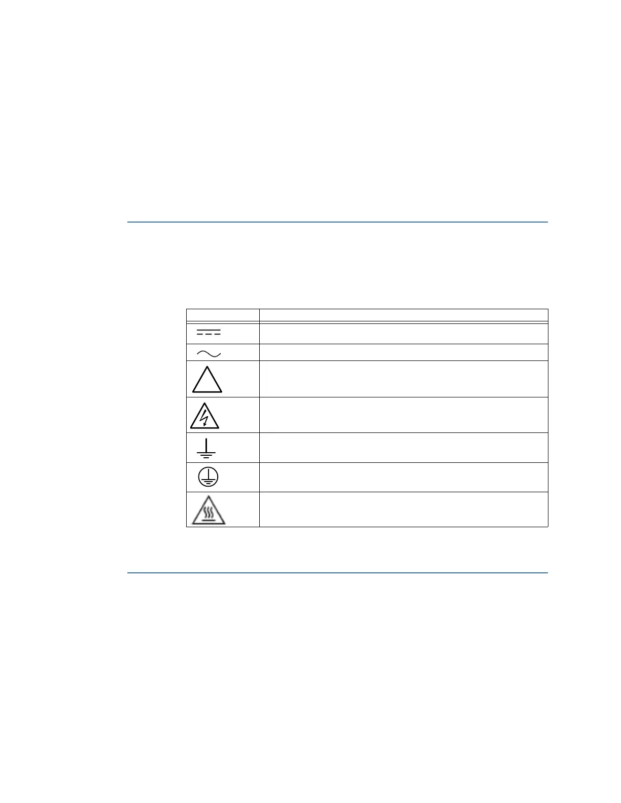
Warning symbols
Table 1 explains the meaning of warning symbols that may appear on the G500 or in this
manual.
Table 1: Warning symbols that appear on the G500 and in this manual
The relevant circuit is direct current.
The relevant circuit is alternating current.
Caution: Refer to the documentation for important operation and
maintenance instructions. Failure to take or avoid specified actions
could result in loss of data or physical damage.
Warning: Dangerous voltage constituting risk of electric shock is
present within the unit. Failure to take or avoid specified actions could
result in physical harm to the user.
Earth/Ground Terminal
Protective Ground Terminal
Caution: Hot Surface
Hardware overview
The G500 is built on a flexible, high-performance, upgradeable COM express platform
powered by one of two CPU modules, either an AMD RX-427BB 4-core 2.7GHz (max turbo
frequency 3.6 GHz) CPU with 16 Gigabytes of soldered on DDR3 ECC memory for best
performance at a limited (+60
°C) maximum operating temperature, or an AMD RX-225FB 2
core 2.2 GHz (max turbo frequency 3.0 GHz) CPU with 8 Gigabytes of soldered on DDR3 ECC
for a wider operating temperature (+70
°C). The G500 is distinguished by the noticeable lack
of a hard drive and fan, employing instead the rugged and reliable Solid State Drive (SSD)
mass storage and engineered heat sink.
Symbol Description