CHAPTER 4: INTERFACES
G500 SUBSTATION GATEWAY INSTRUCTION MANUAL GE INFORMATION 41
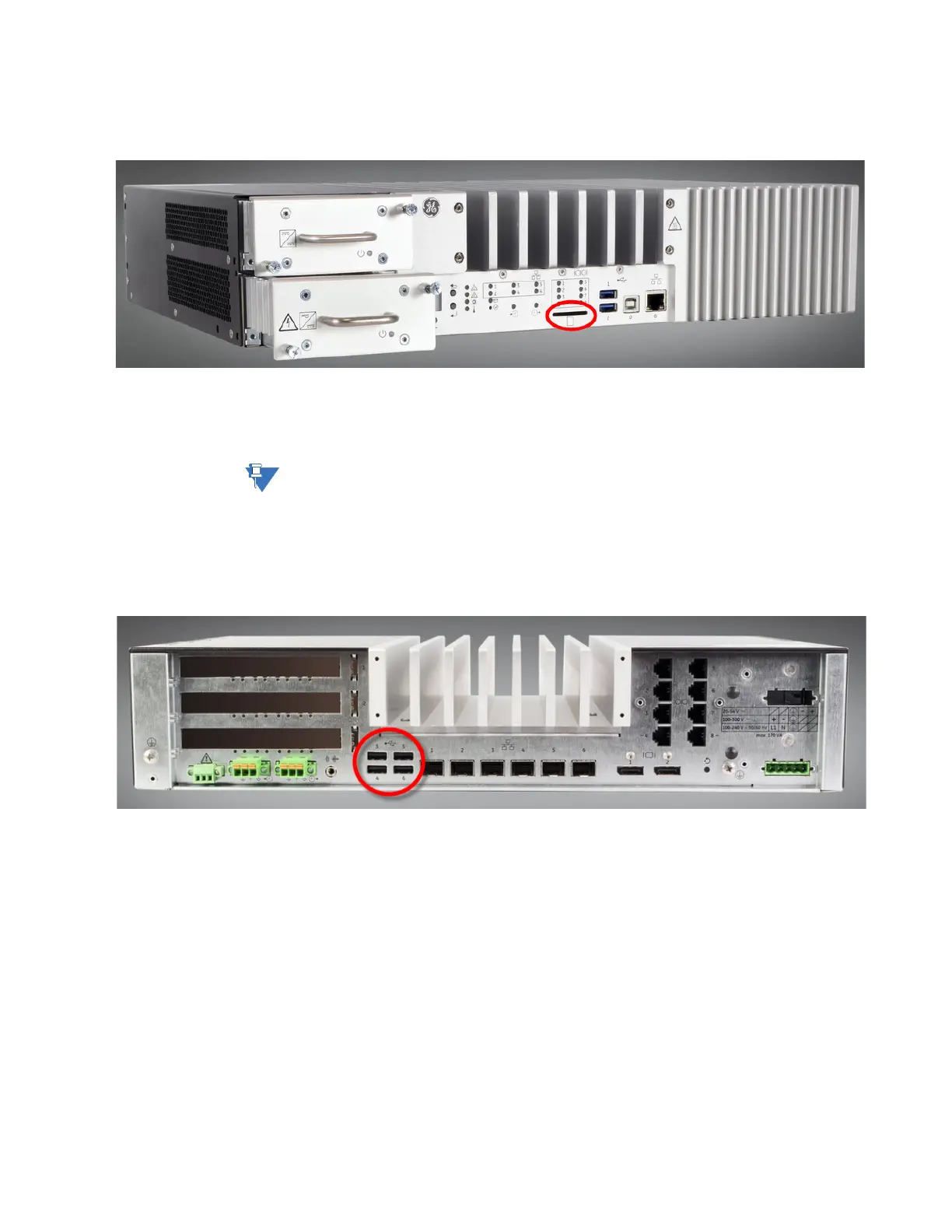
SD Card
At the front of the unit a SD card slot is available.
The SD card slot supports SD, SDHC and SDXC SD-Cards according to Version 1.0, Version
2.0 and Version 3.0.
The SD-Card slot has a push-pull mechanism. Put the card into slot and push it until you
feel some
resistance. Push the card again, if you want to remove it from the slot.
The SD Card is supported only for the Windows Operating System.
USB 2.0
At the rear of the unit four USB 2.0 A connectors are located. Main purpose of these
connectors is to enable installation personnel to connect Mouse, Keyboard and equivalent
equipment for initial configuration of the device.
Each USB 2.0 A connector is fused separately. For normal operation don’t exceed 0.9 A per
connector. The cumulative current draw of all four ports is limited to 1A due to thermal and
power budget restrictions.
The maximum cable length for USB 2.0 cables is 3m (=118in).
Display Port
At the rear of the unit two Display Port connectors are located. The interfaces are DP++
compliant, and are used mainly to enable installation personnel to connect a display for
the initial configuration of the device. Each display port is capable of supporting two
suitable displays via Multi Stream Transport (MST).