GEK-113285A G650 Generator Protection & Control System 6-37
6 ACTUAL VALUES 6.3 METERING
6
6.3.2.3 POWER
Actual> Metering > Secondary Values > Power
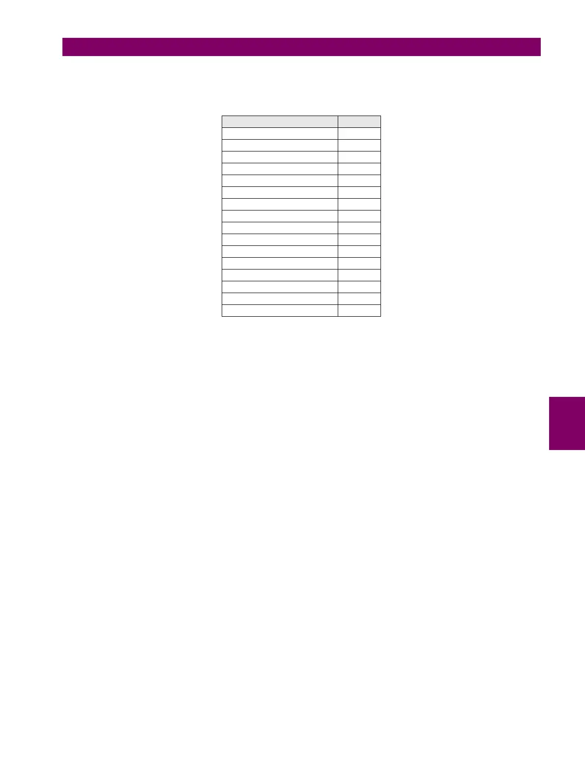
Table 6–43: POWER SECONDARY VALUES
NOTE: If voltage inputs are configured in Delta connection and the Auxiliary Voltage input is set as VX or VN, measure-
ments of single phase power value cannot be duly calculated, and therefore, its value will be zero. Measurement for single
phase power value only will be provided when Wye connection is selected or when Delta connection and VN as Auxiliary
Voltage is selected in General Settings main menu. For the three-phase power value, the system uses the ARON method,
or two-wattmeters method.
DESCRIPTION UNITS
Phase A Apparent Pwr VA
Phase B Apparent Pwr VA
Phase C Apparent Pwr VA
Phase A Real Pwr W
Phase B Real Pwr W
Phase C Real Pwr W
Phase A Reactive Pwr VARS
Phase B Reactive Pwr VARS
Phase C Reactive Pwr VARS
3 Phase Apparent Pwr VA
3 Phase Real Pwr W
3 Phase Reactive Pwr VARS
Phase A Power Factor N/A
Phase B Power Factor N/A
Phase C Power Factor N/A
3 Phase Power Factor N/A
 Loading...

