GEK-113285A G650 Generator Protection & Control System 2-5
2 PRODUCT DESCRIPTION 2.3 ORDERING CODE
2
2.3ORDERING CODE
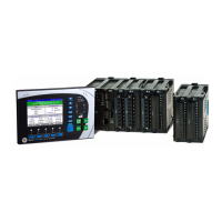
G650 units are supplied as ½ 19” rack, 6 units high, containing the following modules: power supply, CPU, I/O modules,
communication modules. The required information to completely define an G650 model is shown on Table 2–1:
Table 2–1: ORDERING CODE
Notes:
(1) The digit selected for option G must be equal or higher than the digit selected for option F for models including boards 4 and 5.
G65
0
- - - F - G - - - - - DESCRIPTION
B Basic Display (4x20 characters) and basic protection functionality
(see Note 2)
M Graphic Display (240x128 pixels) with Standard Symbols and basic
protection functionality (see Note 2)
N Graphic Display with IEC symbols (240x128 pixels) and basic
protection functionality (see Note 2)
E Basic Display (4x20 characters) and enhanced protection
functionality (see Note 2)
C Graphic Display (240x128 pixels) with Standard Symbols and
enhanced protection functionality (see Note 2)
D Graphic Display with IEC symbols (240x128 pixels) and enhanced
protection functionality (see Note 2)
REAR SERIAL COMMUNICATIONS BOARD 1
F None
A Redundant RS485
P Redundant plastic fiber optic
G Redundant glass fiber optic
X Redundant RS485 + fiber remote CAN bus I/O
Y Redundant plastic fiber optic + fiber remote CAN bus I/O
Z Redundant glass fiber optic + fiber remote CAN bus I/O
C Cable Remote CAN Bus I/O
M RS485 + cable Remote CAN Bus I/O
REAR ETHERNET COMMUNICATIONS BOARD 2
B 10/100 Base TX
C 10/100 Base TX + 100 Base FX
D 10/100 Base TX + Redundant 100 Base FX
E Redundant 10/100 Base TX
I/O BOARD IN SLOT F
1 16 Digital Inputs + 8 Outputs
2 8 Digital Inputs + 8 Outputs + 2 trip/close circuit supervision circuits
4 32 Digital Inputs
5 16 Digital Inputs + 8 Analog Inputs
I/O BOARD IN SLOT G
0 None
1 16 Digital Inputs + 8 Outputs
4 32 Digital Inputs (see Note 1)
5 16 Digital Inputs + 8 Analog Inputs (See Note 1)
AUXILIARY VOLTAGE
LO 24-48 Vdc (range 19.2 – 57.6)
HI
110-250 Vdc (range 88 – 300)
120-230 Vac (range 96 – 250)
LOR Redundant LO
HIR Redundant HI
5 Procome, Modbus® RTU,TCP/IP
ENVIRONMENTAL PROTECTION
- Without Harsh (Chemical) Environment Conformal Coating
H Harsh (Chemical) Environment Conformal Coating