5-92 G650 Generator Protection & Control System GEK-113285A
5.5 CONTROL ELEMENTS 5 SETTINGS
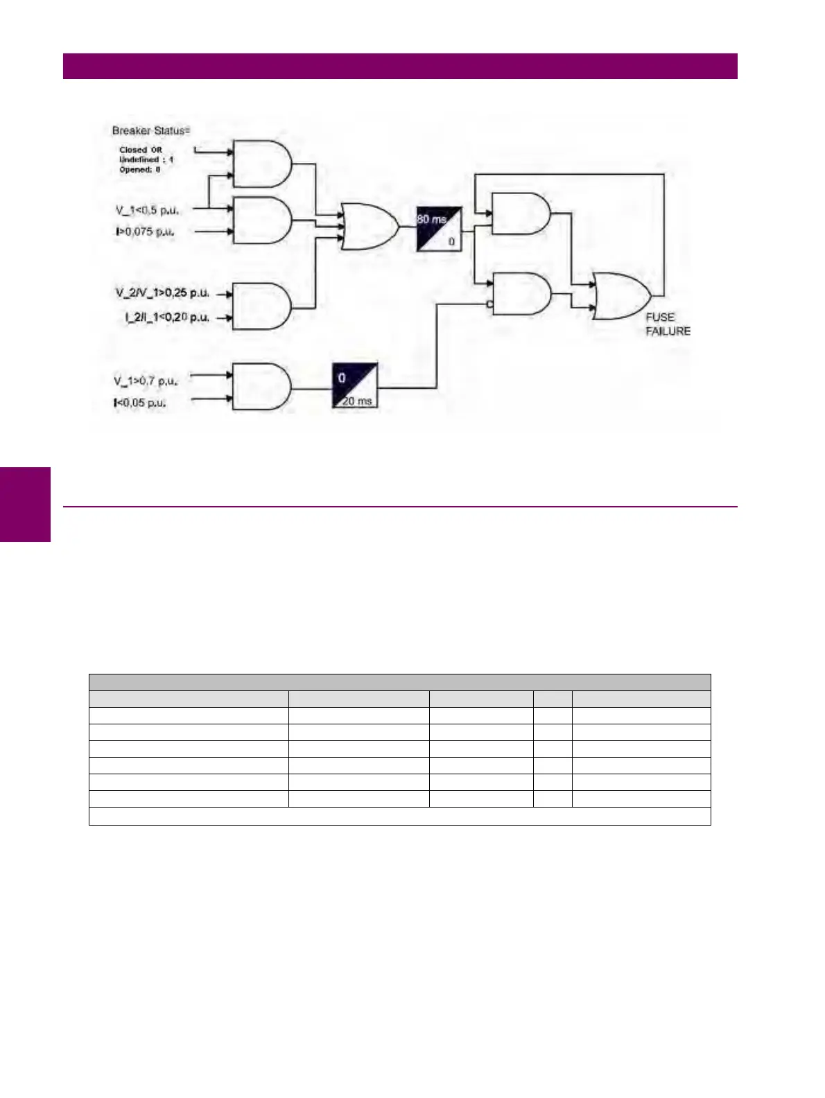
Figure 5–21: FUSE FAILURE ELEMENT BLOCK DIAGRAM
5.5.7 PULSE COUNTERS
The G650 includes eight pulse counters, each pulse counter stores the activation number of the input set to that pulse
counter. This value can be multiplied for a factor selectable by setting.
The inputs used in this pulse counter function can be selected from all the available in the G650 device. Take into account
that the input/output settings are both set for the generic input as well as for the pulse counter input, e.g. Debounce time.
The settings for this function can be found at Setpoint > Control Elements > Pulse Counters
Table 5–87: PULSE COUNTERS SETTINGS
Pulse Counters settings are:
CntPulses Enabled: Enable/disable each pulse counter.
CntPulses Name: Each pulse counter can have a configurable user name.
CntPulses Factor: This is the factor multiplier applied to the input activations number stored in the
pulse counter, providing possibilities to adjust the obtained value to any scale. It the
"CntPulses Factor X" is set to zero it will take no effect.
SETPOINT > CONTROL ELEMENTS > PULSE COUNTERS
SETTING DESCRIPTION NAME DEFAULT VALUE STEP RANGE
Pulse counter enabling setting CntPulses Enabled X DISABLED N/A [DISABLED – ENABLED]
Name of the pulse counter CntPulses Name X Pulse Counter X N/A N/A
Multiplier factor for the pulse counter CntPulses Factor X 1.000 0.001 [0.000 : 65000.000]
Overflow value for the pulse counter CntPulses Overflow X 65535 1 [0 : 1000000]
Board selection for the pulse counter CntPulses Board Origin X F N/A [F,G,H,I]
Input index inside the selected board CntPulses Input Origin X 1 1 [1 : 32]
Note: X is the pulse counter index, up to 8.


 To Next Page