GEK-113285A G650 Generator Protection & Control System 9-13
9 COMMISSIONING 9.11 TIME OVERCURRENT (51PH, 51PL, 51N, 51G)
9
9.11 TIME OVERCURRENT (51PH, 51PL, 51N, 51G)
Set the relay to trip for the protection element being tested. Configure any of the outputs to be activated only by the
protection element being tested.
Apply 0.9 times the Pickup current and check that the relay does not trip.
Apply 1.5 times the Pickup current. The relay should trip according to the time corresponding to its set curve.
Apply 5 times the Pickup current. The relay should trip according to the time corresponding to its set curve.
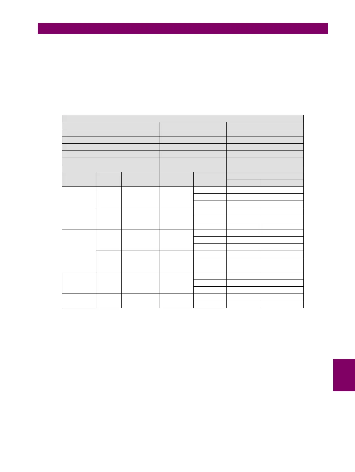
PROTECTION ELEMENT SETTINGS (51PH, 51PL, 51N, 51G )
SETTING VALUE UNIT
FUNCTION ENABLED
INPUT PHASOR (DFT)
PICKUP LEVEL 1 A
CURVE MODIFY FOR EACH TEST
TD MULTIPLIER MODIFY FOR EACH TEST
VOLTAGE RESTRAINT DISABLED
ELEMENT PHASE CURVE TYPE DIAL TIMES
IPICKUP
TRIPPING TIMES (SEC)
EXPECTED ADMISSIBLE
51PH IA IEEE Ext Inv 0.5 0.9 NA
1.5 11.34 [11.00 – 11.60]
5 0.648 [0.600 – 0.710]
IB IEC Curve A 0.05 0.9 NA
1.5 0.860 [0.750 – 0.950]
5 0.214 [0.200 – 0.300]
51PL IC IEEE Ext Inv 0.5 0.9 NA
1.5 11.34 [11.00 – 11.60]
5 0.648 [0.600 – 0.710]
IB IEC Curve A 0.05 0.9 NA
1.5 0.860 [0.750 – 0.950]
5 0.214 [0.200 – 0.300]
51N IC IEEE Ext Inv 0.5 0.9 NA
1.5 11.34 [11.00 – 11.60]
5 0.648 [0.600 – 0.710]
51G IG Definite Time 2 0.9 NA
5 2.000 [1.900 – 2.100]