3-34 F650 Digital Bay Controller GEK-113000T
3.2 HUMAN MACHINE INTERFACE (HMI) 3 HUMAN INTERFACES. SETTINGS & ACTUAL VALUES
3
3.2.5 TEXT MENUS
3.2.5.1 NAVIGATION IN TEXT MENU
Text menu is available for all models, this is the main menu for visualizing actual values, metering, changing settings, etc.
through the HMI. In models with graphical display (M in ordering code) besides this text main menu there are several
screens providing more performance for control purposes.
Press (or rotate left or right) the shuttle key to enter the main menu, starting from the standby screen (default main screen).
The default main screen can be accessed pressing ESC key till it appears. In all the navigation press the shuttle key to
select the desired header display (top-level menu). Each press of the shuttle key advances through the main heading
pages as illustrated below. To return to previous menus press the ESC key. To move inside the top-level menu without
changing to other low levels, rotate the shuttle key left to move up and right to move down.
When rotating the shuttle key the selected menu is marked by a single scroll bar character. The mark (>) in the right part of
any menu means that contains more than one level.
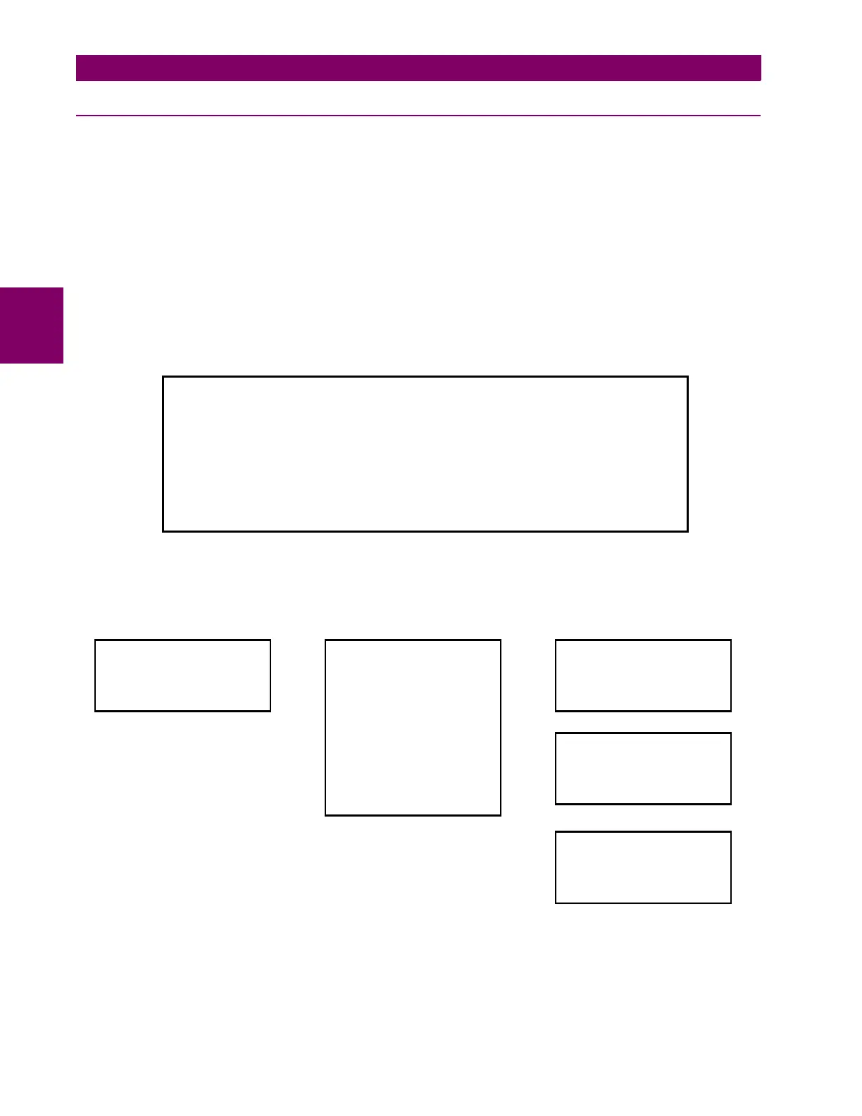
Figure 3–17: Shows an example of main menu navigation:
Figure 3–17: NAVIGATION IN MAIN TEXT MENU
Symbol Action Performed Navigation in menu
ENTER Press Shuttle Key Enter next level
ESCAPE Press Esc Key Exit to previous level
L-R Rotate Shuttle Key Move up and down in the same level
L Rotate left Shuttle Key Move up in the same level
R Rotate right Shuttle Key Move down in the same level
Menu selection Menu selection
> More menus to display More menus to display
F650 3.40 (4.10)
GENERAL ELECTRIC
F650MZDF2G1HIR
19200N81: MODBUS : 254
Actual Values
Snapshot event
Fault report
View Settings
Change Settings
Date & Time
Commands
Passwords
Select Main Screen
Select Language
Å
Return
Front Panel >
Status >
Metering >
Inputs/Outputs >
Product Setup >
System Setup >
Protection Element>
Control Elements >
Logotype >
Metering >
All >
Å
Return
ENTER
ESCAPE
ENTER
ESCAPE

 Loading...


