7 Protection Parameter Settings
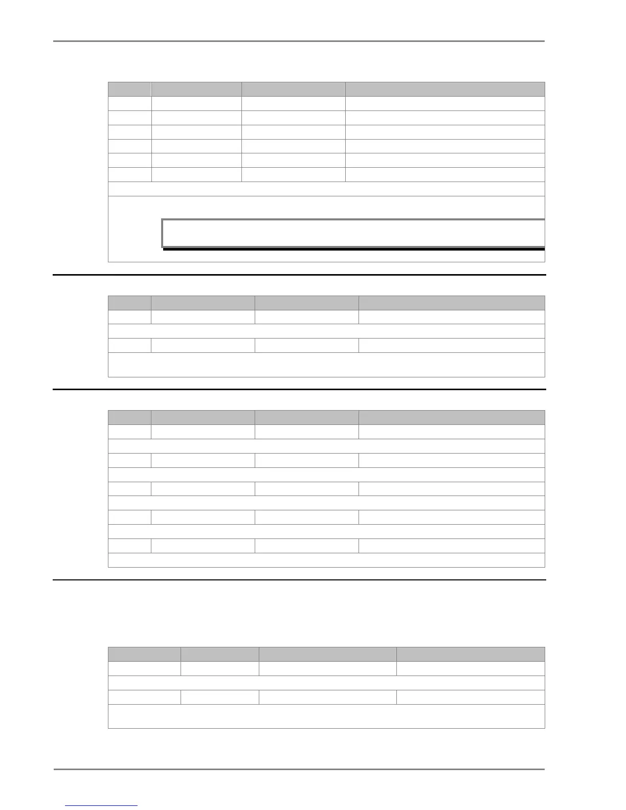
13. ANDEQ B Op Time 1 S 1s to 3600s step of 1s
16. ANDEQ C Rst Time 1 S 1s to 3600s step of 1s
17. ANDEQ D Op Time 1 S 1s to 3600s step of 1s
18. ANDEQ D Rst Time 1 S 1s to 3600s step of 1s
These settings specifies the operating/reset time delay allocated to the logic AND equation.
Note: The above setting parameters from serial no 9 to 18 are available under “IO Mask” in
P50 Agile Configurator.
2.10 DISTURBANCE RECORD Settings
1. Password 0000 0000 to zzzz
This setting specifies to enter the set password
This setting sets the trigger point as a percentage of the duration. For example, the default setting, which is set to 50% (of 1.0s)
prefault and 0.5s post fault recording times.
2.11 COMMISSION TEST Settings
Sr. No Parameter Defaults setting Setting/Ranges
1. Password 0000 0000 to zzzz
This setting specifies to enter the set password
2. Test Mode Disabled Disabled, Test Mode, Contacts Blocked
This setting allows secondary injection testing to be performed on the relay itself.
0 = not operated, 1 = operated
This setting is used to select the output relay contacts that will be tested when the Contact Test cell is set to Apply Test.
4. Contact Test No Operation No Operation, Apply Test, Remove Test
This setting is used to test the relay output contact operation.
5. Test LEDs No Operation No Operation / Apply Test
This setting is used to test the 4 no’s programmable LED’s.
2.12 GROUP Settings
The following settings are common to GROUP 1 and 2.
2.12.1 SYSTEM CONFIG SETTINGS
Sr. No Parameter Default setting Setting Range
1. 2nd Harmonic Disabled Enabled/Disabled
This setting is used to enable or disable the 2nd Harmonic blocking of the overcurrent protection.
2. 2ndHarm Thresh 20% 5% to 70% step 1%
This setting is used to specify the 2nd Harm Threshold value. If the level of 2nd harmonic/fundamental in any phase current or neutral
current exceeds the setting, the overcurrent protection will be blocked as selected.

 Loading...


