7 Protection Parameter Settings
3. IN2>3 Time Delay 1 S 0 to 200s step 0.01s
This setting determines the time-delay for the definite time setting if selected for third stage of derived earth fault element.
This time multiplier setting is used to adjust the operating time of the IEC/UK IDMT characteristic.
5. IN2>3 Time Dial 1 0.01 to 100 step 0.01s
This time multiplier setting is used to adjust the operating time of the IEEE/US IDMT curves.
6. IN2>3 Reset Char DT DT/IDMT
This setting determines the type of reset/release characteristics. IDMT applicable for IEEE curves only.
This setting determines the reset/release time for IEEE IDMT characteristic
8. IN2>3 tRESET 0.01 S 0 to 100s step 0.01s
This setting determines the reset/release time for Definite Time (DT) and all IDMT curve
9. IN2>3 2H Blocking Disabled Enabled/Disabled
This setting determines the enabling/disabling of blocking third stage derived earth fault element due to presence of inrush current.
If IN2>3 Blocking and 2nd Harmonic both settings are enabled, then (IN2>3) trip command will be blocked in case 2nd harmonics content
in any phase is above the 2ndHarm Thresh. and fundamental current is below I> lift 2H setting. (Set in SYSTEM CONFIG Menu.)
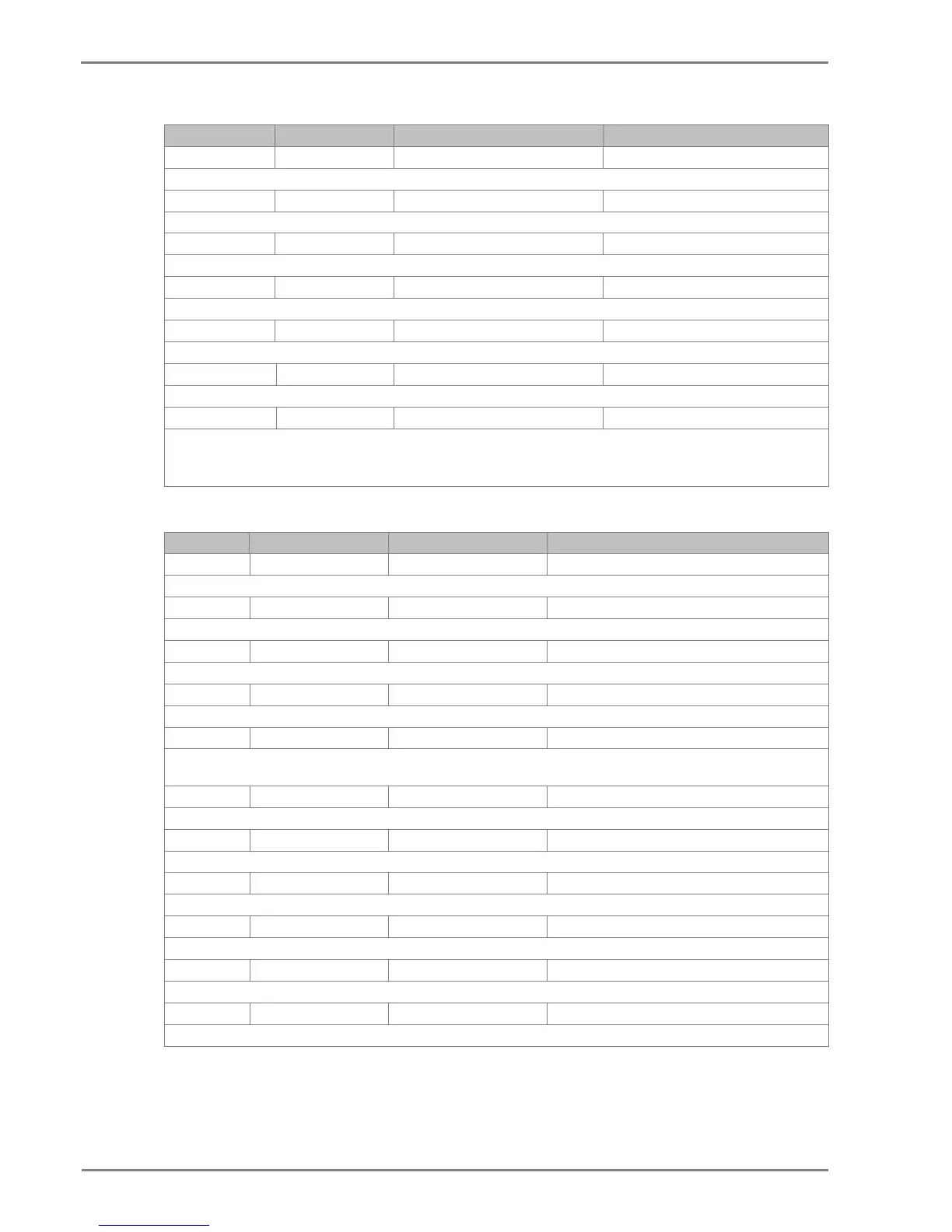
2.12.5 THERMAL OVERLOAD Settings
Sr. No Parameter Default setting Setting Range
1. Inh Trip Dur st Disabled Disabled/Enabled
This setting enables/disables the thermal inhibition on starting
2. K Coefficient 3*In 0 to 10*In in step 1*In
This setting determines the value of the negative sequence contribution factor in the thermal image
This setting enables/disables the thermal trip function
4. Thermal Alarm Enabled Disabled/Enabled
This setting enables/disables the thermal alarm function
This setting determines the thermal state threshold corresponding to a percentage of the trip threshold at which an alarm will be
This setting determines the value of overload time constant.
7. Thermal ConstΤ2 20 Mins 1 to 360 min step 1
This setting determines the value of starting time constant.
8. Cooling ConstTr 60 Mins 1 to 999 min step 1
This setting determines the value of cooling time constant.
This setting enables or disables the thermal lockout function which inhibits restart if the thermal state exceeds Lockout threshold.
10. Lockout Thresh. 90 % 25 to 100% in step 1%
This setting determines the threshold value for thermal inhibition of start
11. K 1.05 1 to 1.5 step 0.01
This setting specify the k constant of thermal over load function

 Loading...


