to any function from I/O configuration menu. The function can be assigned to any input by entering the
values to them either 0 or 1 i.e. 0 = not assigned and 1 = assigned.
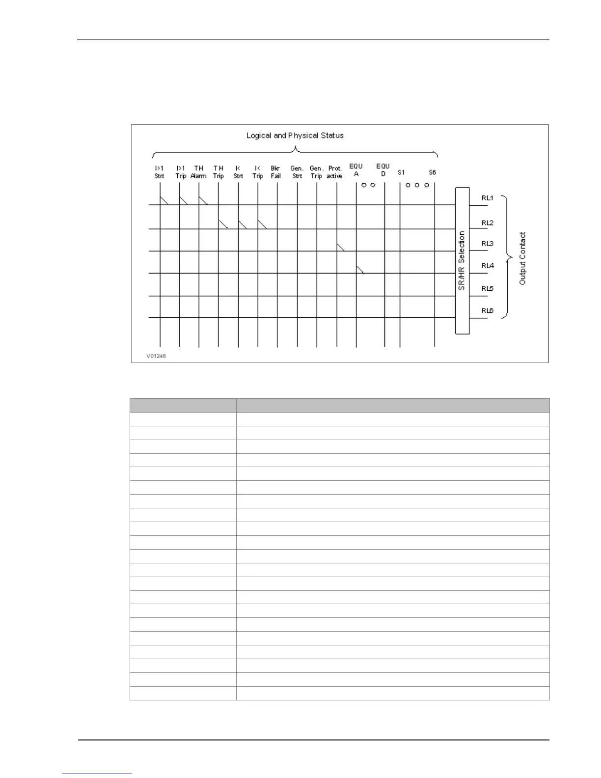
The following diagram explains the assignment process to relay either by UI or P50 Configuration.
Figure 1: Output contact configuration logic
The following functions can be assigned to the relay contacts.
Start detected in phase A
Start detected in phase B
Strt L3 Start detected in phase C
Strt I>1 Start O/C stage 1
Strt I>2 Start O/C stage 2
Strt I>3 Start O/C stage 3
Start Neg seq. O/C stage 1
Start Neg seq. O/C stage 2
Strt I2>3 Start Neg seq. O/C stage 3
StrtIN1>1 Start Measured E/F stage 1
StrtIN1>2 Start Measured E/F stage 2
StrtIN1>3 Start Measured E/F stage 3
Start Derived E/F stage 1
Start Derived E/F stage 2
StrtIN2>3 Start Derived E/F stage 3
THOL Alm Start Thermal Alarm
Strt I< Start Loss of load
Strt CBF Start Breaker Failure
Block O/C protection during CB Fail
Block E/F protection during CB Fail

 Loading...


