– 18 –
Membrane Keypad
The door panel must be removed to access the membrane keypad (see Door Panel).
• When removing the membrane keypad, peel the keypad from right to left.
• When installing, make sure the membrane button areas and lights align with the keypad.
• On models with an LED display, the display is held in place by 2 Phillips head screws.
Note: When replacing the keypad membrane, always run the Factory Test Mode to calibrate the keypad
membrane to the control board.
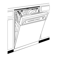
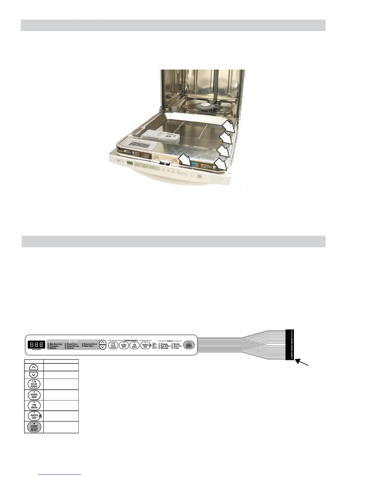
Door Panel
The door panel covers the main control board, detergent cup, vent fan, motor, louver, and door-interlock
switch.
The outer door panel is held in place by 12 screws (5 Phillips head screws per side and two
1
/
4
-in. hex
head screws at the bottom).
Note: Ribbon cable(s) connect the keypad membrane (3-digit display on some models) to the control
circuit board. Due to the ribbon length, care must be taken when removing the door panel to ensure
that the ribbon cable(s) are not damaged.
1
PADS
CONNECTOR PINS
13 & 15
12 & 17
12 & 16
12 & 15
11 & 15
11 & 16
11 & 17
Note: When troubleshooting, always check resistance between pins 18 and 19:
• 7-keypad membrane should read approximately 22K Ω.
• 6-keypad membrane should read approximately 75K Ω.
When a control pad is pressed, continuity is present on the corresponding pins
(see chart). Example: If the HEATED DRY pad is pressed, you should have
continuity between pins 12 and 17. To locate pin numbers, note location of pin
1 for reference point. (See graphic.)
7-Keypad Membrane Shown
 Loading...