41
Motor Assembly (cont.)
Specific failures associated with the motor assembly can initiate error codes E3, and
E15 through E25. (See Service Test Mode.)
Method B:
1. Remove the service panel. (See Service Panel.)
2. Remove the single Phillips-head screw that holds the right front leg of the inverter to
the base pan.
3. Slide the inverter rearward to clear the guides that hold the rear of the inverter to the
base pan.
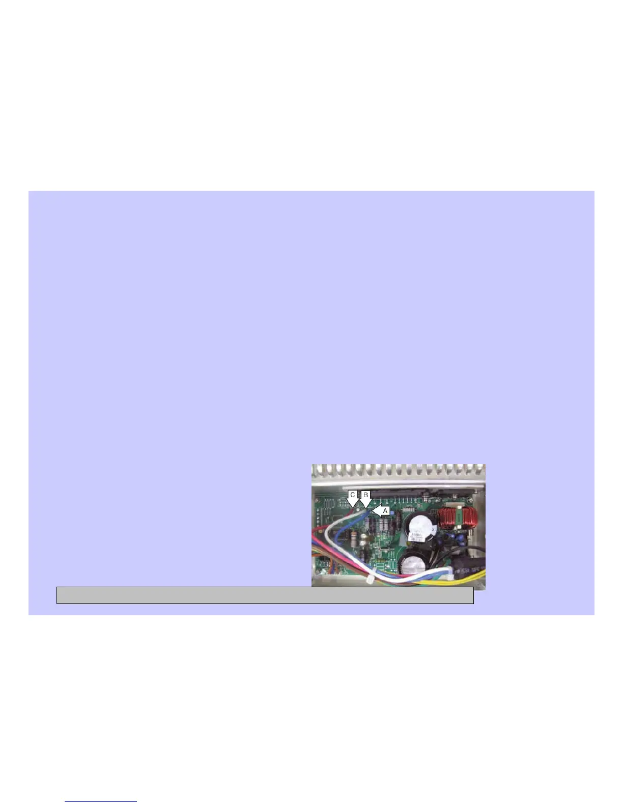
4. Position the inverter to access the inverter board.
5. On the inverter board, check for an approximate resistance value of 6 ohms between
any two of the three terminals:
• A to B (Blue to white) – 6 Ω
• A to C (Blue to red) - 6 Ω
• B to C (White to red) - 6 Ω
CONFIDENTIAL AND PROPRIETARY INFORMATION-NOT FOR PUBLIC DISCLOSURE. September 2008
 Loading...