Description and operation
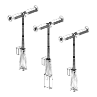
Operating d evice of circuit- breaker
GE Information L14- 005EN/05
2/6
11- 2016
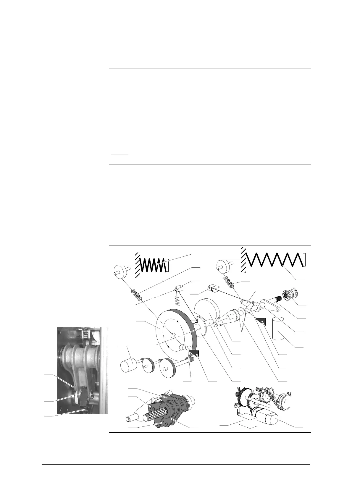
Description of the mechanism
Drive shaft
D The main shaft (1) is linked up to the the circuit- breaker pole by means
of a cylinder (2).
D A damper (4) is linked up to the lever (32).
D In the “CLOSED” position, the main shaft (1) rests on the opening latch
(6) by means of the lever (5).
D In the “OPEN” position, the lever with roller (11) rests on the closing
cam (10).
D The opening spring (3) activates the lever (33) by means of the chain
(34). This spring is a pressure helical type.
NOTE
: The levers (5)- (11)- (32) (33) form one piece only.
Closing shaft
D On the closing shaft (7) are placed :
- The inertia flywheel (8).
- The closing cam (10).
- The cam (26) that engages the limit switch (17) of the motor (12).
D The closing spring (9) activates the inertia flywheel (8) by means of the
chain (15). This spring is a pressure helical type.
The rotation torque - created on the inertia flywheel (8) by means of the
loaded closing spring (9) - is balanced by closing latch (14) / roller (16).
33
Diagram
11
34
5
32
33
17
12
34
2
1
26
32
7
30
10
14
8
11
5
31
6
33
3
15
17
9
12
16
11
4