Description and operation
Operating d evice of circuit- breaker
GE Information L14- 005EN/05
3/6
11- 2016
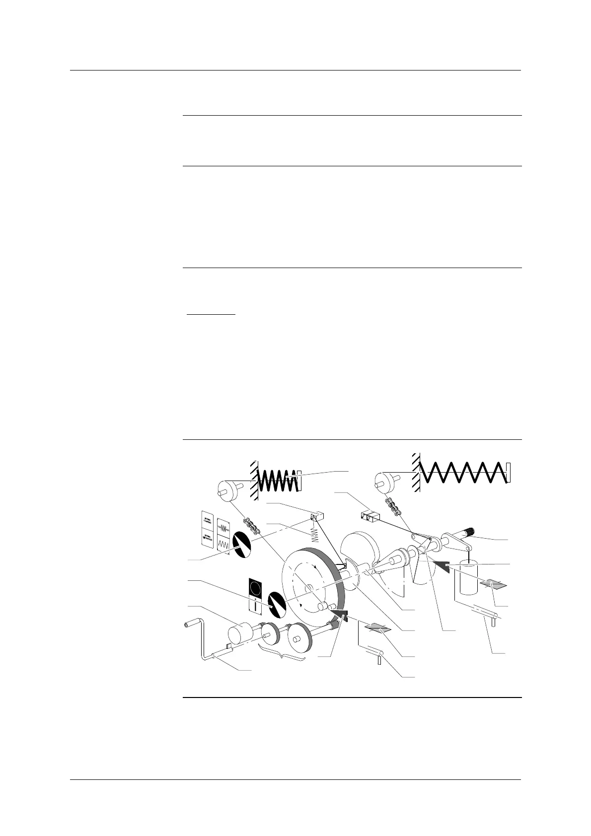
Auxiliary fittings
Reloading the closing
spring
The closing spring (9) is loaded by means of the reducing gears (13) and the
motor (12).
Auxiliary electric
fittings
D The auxiliary contacts (30) are activated by a rod and a lever (31), the
latter is activated by the main shaft (1).
D The limit switch of the motor (17) is activated by the cam (26)
The cam (26) is installed on the closing shaft (7).
D The closing latch (14) and the opening latch (6) are electrically activated
by coils (22) “Closing” and (27) “Opening”.
Auxiliary mechanical
fittings
D The operating mechanism can be activated by the manual levers (24)
“Closing” and (28) “Opening”.
W ARNING
: Operating the mechanism by the manual levers (24) “Closing”
and (28) “Opening” overrides electrical interlocks. Ensure it is electrically safe
to operate the equipment when using these levers to defeat electrical inter-
locks and lockouts.
D The indicator (29) gives the “OPEN” or “CLOSED” positions of the circuit-
breaker. An operation counter gives the number of realized operations.
D The indicator (23) gives the “CHARGED” or “DISCHARGED” states of the
closing spring.
D If the auxiliary current supply fails, the hand- held crank (21) permits the
closing spring to be fully charged.
Diagram
28
7
26
24
30
22
13
14
17
34
23
29
9
12
21
6
31
27
1