Installation
Coupling of column and chambers
GE Information L31- 7138EN/02
13/16
11- 2016
Final coupling, continued
Connection
chambers/column
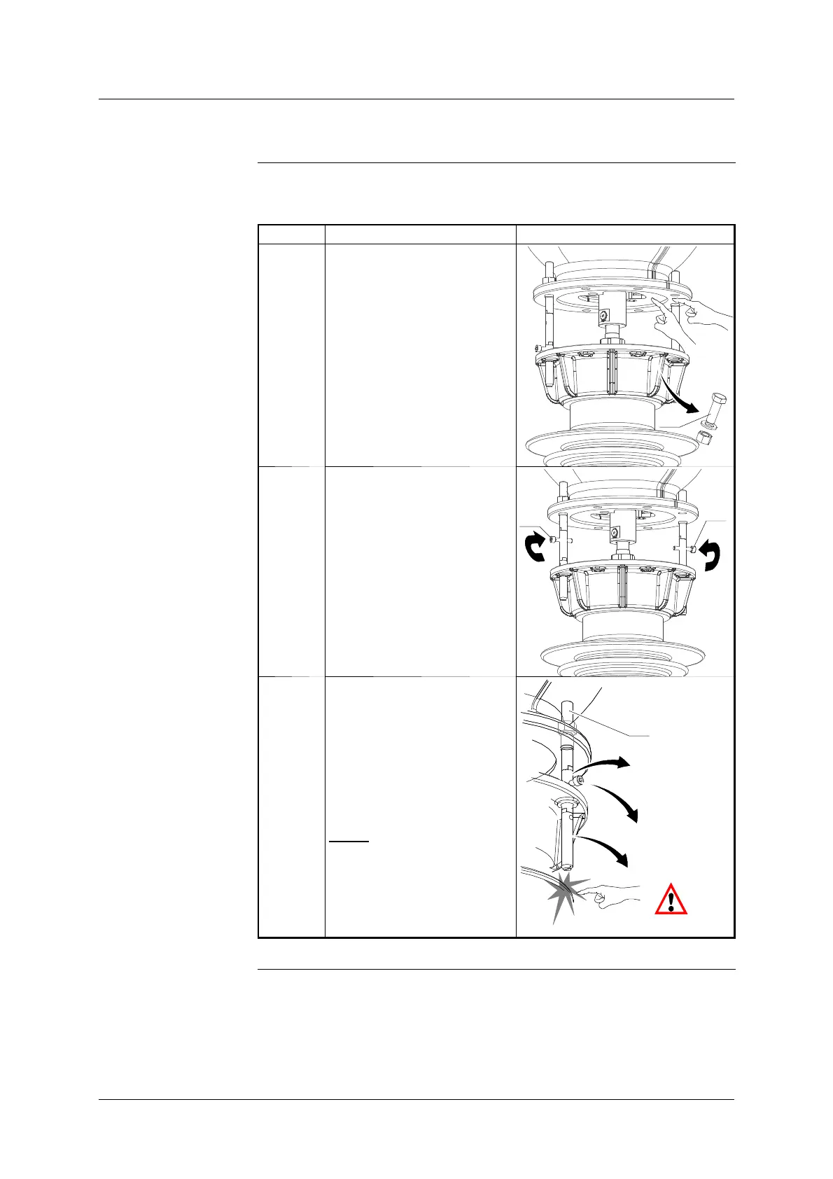
The table below shows the steps for connecting the chambers to the column:
Step Action Illustration
1 Clean the contact surfaces
”A” and ”B” with ISOPRO-
PANOL.
Only coat surface ”B” with
MOLYKOTE M111 lubricant.
Remove the trolley stop fixing
screws (40).
40
A
B
2 Remove the screws (42) from
the centring pins.
42
42
3 Continue to slowly lower the
breaking chamber, removing
the first two sections of cent-
ring pin (30 & 31) when they
are no longer of any use as a
guide, in the following order:
- First section (C)
- Screw (42)
- Second section (B)
NOTE
: The aim of this
operation is to prevent the
centring pins coming into
contact with the porcelain
fins on the column.
30
31
(C)
(B)
(42)
Continued on next page.