Packaging - Shipping and storage
Packaging - Identification - Storage
GE Information L22- 027EN/04
3/6
03- 2017
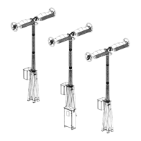
Identifying sub- assemblies and their packagin g
Introduction
Each of the component parts of the circuit breaker (columns, breaking
chambers & actuator) is identified using a plate and coloured stickers.
The identifying marks for each component are also marked on the package.
The pairing- up of the various components is achieved by means of the
following three elements:
S The device’s Individual Test Report (REI)
S The ID plate on each component (column, breaking chamber, actuator)
S The colour of the sticker (columns, breaking chambers & actuator)
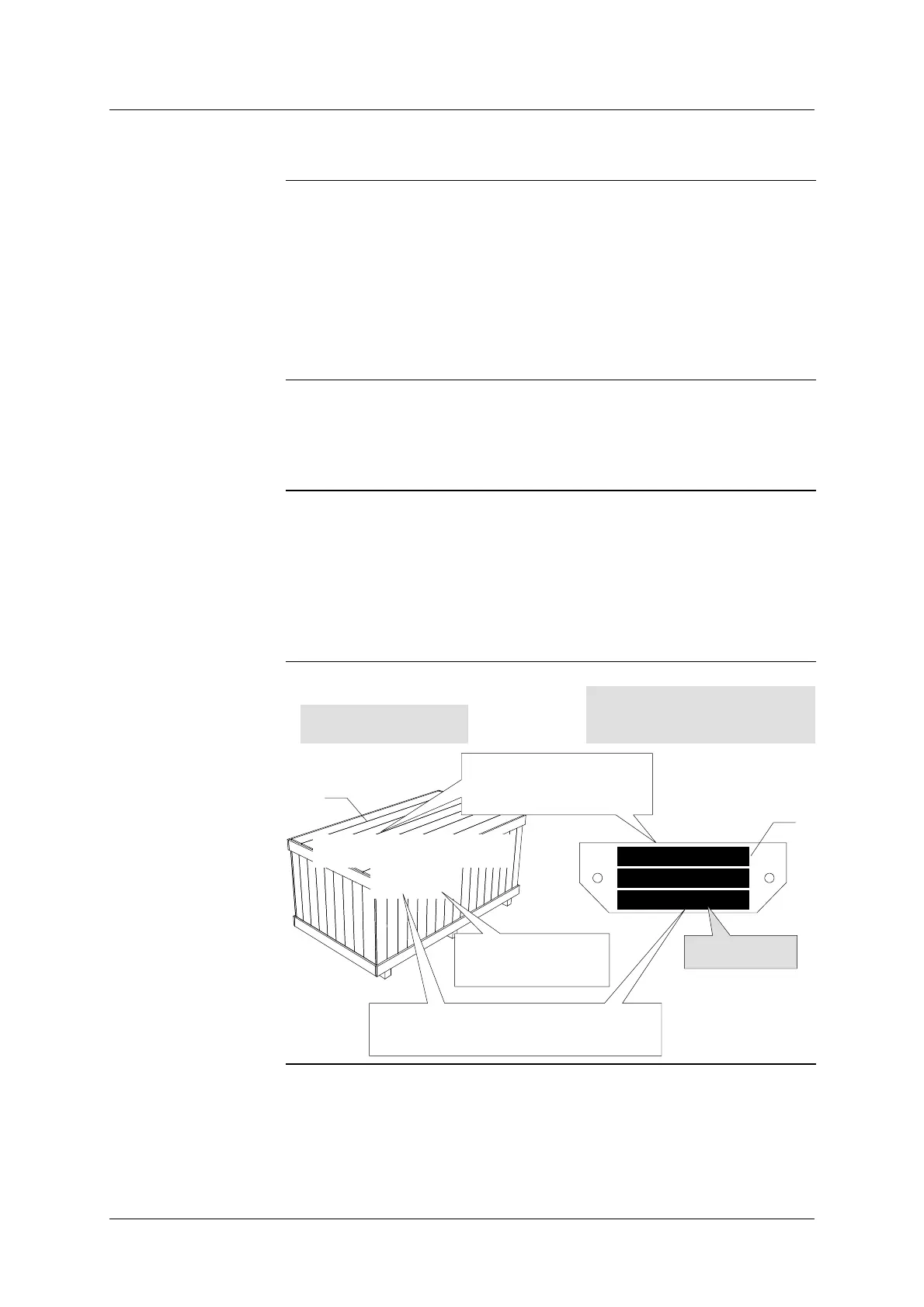
Example of markings
and identification
- Manufacturer’s reference No.: 101 525
- Circuit breaker marked: 01
- Position within the phase: 2
Rules for colour
markings and
identification
- Each phase is identified by a pre- defined colour.
- Phase 1: Red
- Phase 2: Yellow
- Phase 3: Green
(e.g. Phase 2 = all components making up this pole should have one
yellow sticker)
101 525 0010
MANUFACTURER
REFERENCE No.
MARKING OF
PACKAGING CASES
IDENTIFICATION OF
SUB- ASSEMBLIES AND
TOOLING
2
0101
CASE No.
101 525 0010
Serial Number
Mark 01/2
POLE No.
CIRCUIT- BREAKER
IDENTIFICATION No.
1