MA-014 - TRANSFIX DGA 500 User Guide – Rev 1.1 13-Oct-15 Page 16 of 28
Figure 6—10: Communication channels
6.1.3.2 Networking
If Ethernet is enabled and a RJ-45 connection made, relevant network details are shown.
For security reasons, all network details are hidden by default as shown in Figure 6—11,
but these can be software enabled.
Figure 6—11: Networking
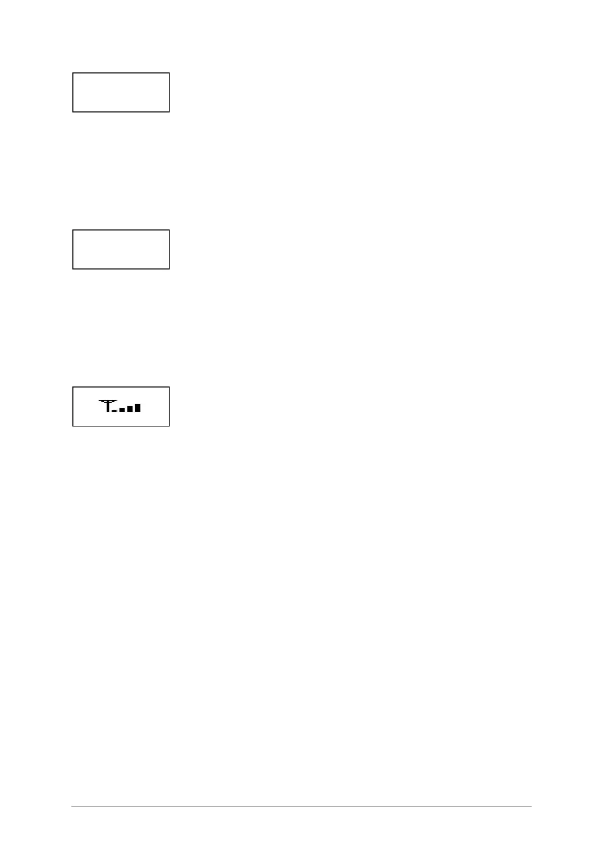
6.1.3.3 Other System Details
Additional information notices reflect the configuration of the product. For example, if a
GSM/GPRS modem is fitted, additional page(s) as shown in Figure 6—12 reflect the
communications provider, signal strength and any problems.
Figure 6—12: GSM / GPRS modem
Notes:
a) Actual product values depend on the installation at any moment in time.
b) Actual parameter format can vary e.g. CO or Carbon Monoxide.
c) See Section 6.2 for a list of defined error codes.
d) System Failure mode limits functionality. Contact the Customer Service Centre.
ChA RTU 1 RS232
19200 0
ChB: ASC 1 GSMGPRS
57600 0
IP: XXX.XXX.XXX.XXX
SUB: XXX.XXX.XXX.XXX
GW: XXX.XXX.XXX.XXX
TCP: 502
vodafone UK
MAJOR GPRS PROBLEM

 Loading...


