49-1000610 Rev. 2 21
INSTALLATION INSTRUCTIONS
Installation Instructions
Drain Pump Kit UPK4 Accessory Installation (Cont.)
DISCONNECT ELECTRICAL
POWER
WARNING
Electrical Shock
Hazard
'HDWKRUVHULRXVLQMXU\FDQUHVXOWIURPIDLOXUHWR
follow these instructions.
• Service by a qualified service technician only.
'LVFRQQHFWSRZHUEHIRUHVHUYLFLQJWKLVSURGXFW
• Reconnect all grounding devices after service.
• Replace all parts and panels before operating.
1
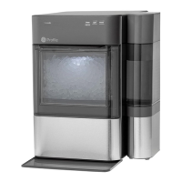
REMOVE ACCESS COVER
Ŷ 8VHDGULOORUD3KLOOLSVVFUHZGULYHUWRUHPRYH
the 2 screws from the access panel as shown
in figure below. Slide the panel in the direction
shown to remove.
Screws
Access
Panel
Slide panel in
this direction
2
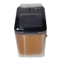
REMOVE DRAIN TUBING
Ŷ Remove the plastic snap ring from the main
drain tube and release the small metal clamp
on the short drain tube which connected outlet
valve. Pull both tube down. Remove the small
metal clamp from the tube. Keep both snap ring
and clamp for pump kit installation
Ŷ Remove the white drain pipe by pulling it down
from the 2 locations shown.
3
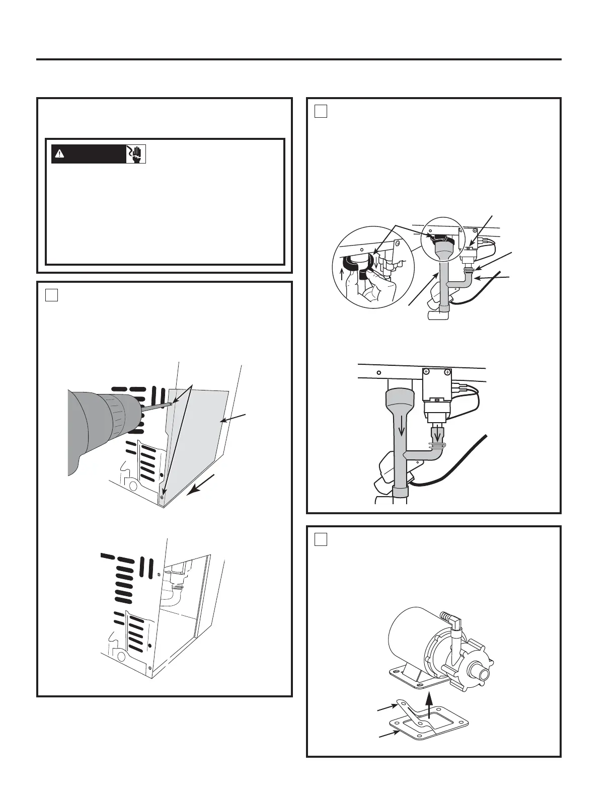
INSTALL RUBBER PAD TO NEW
PUMP
Ŷ Remove the rectangular rubber pad from pump
kit and peel off the white sticker. Attach the
sticky side to the drain pump base.
White Sticker
Rubber Pad -
Sticky side up
Snap
Ring
Short
'UDLQ
Tube
Main
'UDLQ
Tube
Outlet
Valve
Small
Metal
Clamp
 Loading...