49-1000610 Rev. 2 23
INSTALLATION INSTRUCTIONS
Installation Instructions
Drain Pump Kit UPK4 Accessory Installation (Cont.)
8
FINALIZE INSTALLATION
Ŷ Re-install side panel using the screws
removed in step 1.
Ŷ Re-install unit into built-in or free-standing
ORFDWLRQ(1685(7+$712.,1.62&&85
,1:$7(5,1/(725'5$,178%,1*
'RXEOHFKHFNIRUOHDNV
Ŷ Restore potable water supply and restart the
unit. Check unit to ensure proper operation
and to allow a final check for leaks of any kind.
7
CHECK PUMP OPERATION
Ŷ Restore power to the unit.
Ŷ With the unit still in standby mode (ice making
not on) , pour several quarts of water into
the bin. The drain pump should turn on and
pump the water out of the bin, cycling on and
off several times during the process. Pump
cycling is normal since the pump-out rate of
the drain pump is greater than the rate of drain
through the bin.
Ŷ While the pump is discharging water,
7+2528*+/<&+(&.7+((17,5('5$,1
SYSTEM FOR LEAKS.
6
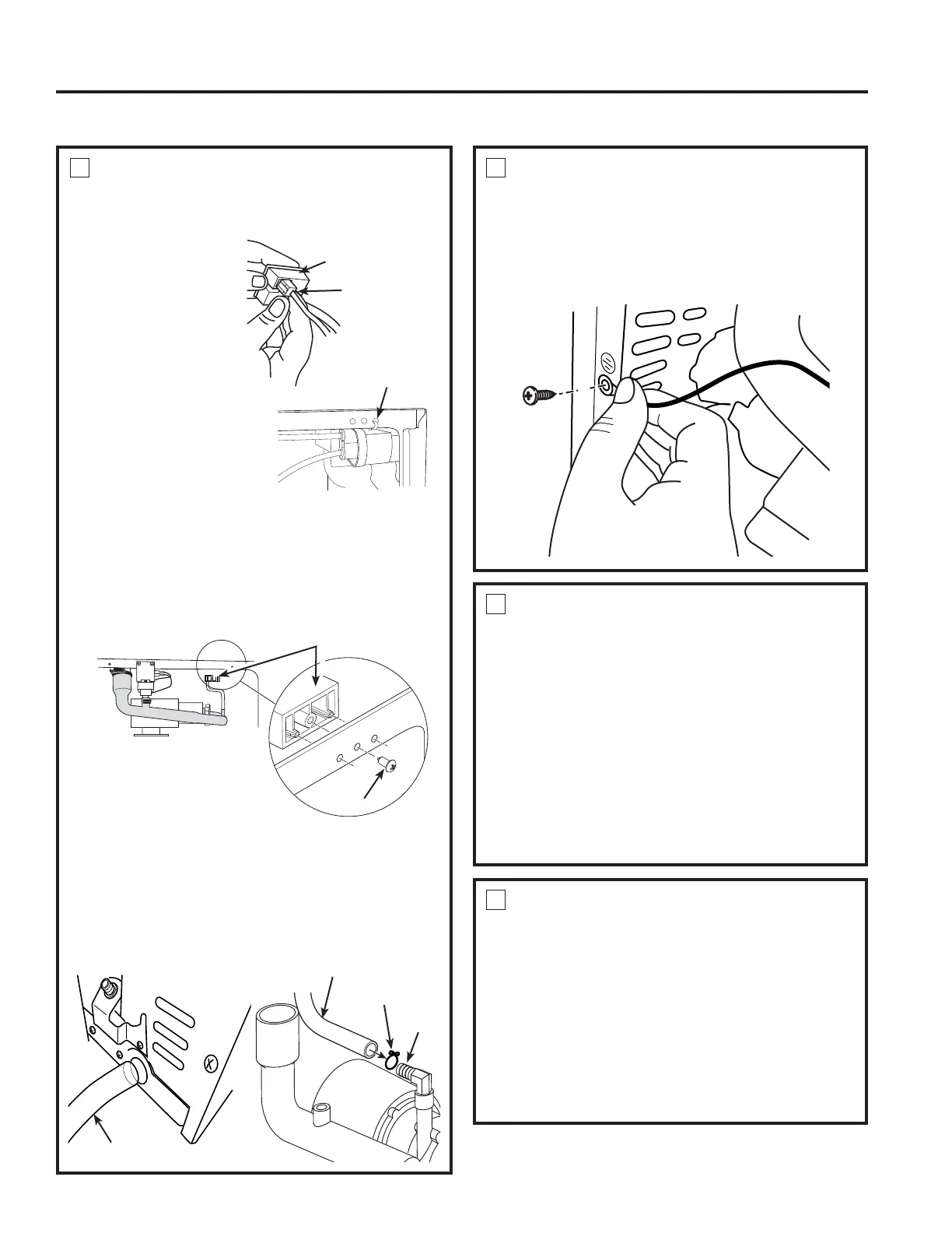
CONNECT DRAIN PUMP TO ICE
MACHINE (Cont.)
Ŷ IMPORTANT Ground the pump to
the machine cabinet using the green ground wire
and screw. The grounding hole is marked with a
grounding symbol.
6
CONNECT DRAIN PUMP TO ICE
MACHINE (Cont.)
Ŷ Locate the male
4-pin white pressure
sensor connector
behind the bracket
hole, loosen the
wire tie and connect
the pig tail to the
pressure sensor
located on the drain
WXEHDVVHPEO\,IWKH
male 4-pin white pressure
sensor connector is not
showing in the access
opening area, locate the
connector in the nearby
machine compartment
area and connect it to pressure sensor on the
drain tube assembly. The 4- pin male connector
within the ice machine will match up with the
4-pin female connector on the pressure sensor.
NOTE: the yellow connector within the ice
machine should not be used.
Attach the pressure sensor assembly in the 3
holes of the flange of the ice machine, as shown,
using the screw provided with the kit.
Ŷ Thread the drain hose into the round hole in the
back of the ice machine case and attach to the
QR]]OHRQWKHWRSRIWKHGUDLQSXPSXVLQJWKH
large metal clamp.
Pressure Sensor
Connector from
,FH0DFKLQH
Pressure Switch
$VV\IURP'UDLQ
Pump
%DFNRI,FH0DNHU
'UDLQ+RVH
'UDLQ+RVH
1R]]OH
Large Metal Clamp
Pressure Switch Assembly
Screw
Lower the pump and make
sure the drain tube is not in
DKRUL]RQWDOSRVLWLRQ
White pressure sensor
connector is tied behind
the flange.