GE Multilin L60 Line Phase Comparison System 5-181
5 SETTINGS 5.5 GROUPED ELEMENTS
5
d) NEGATIVE SEQUENCE DIRECTIONAL OVERCURRENT (ANSI 67_2)
PATH: SETTINGS ÖØ GROUPED ELEMENTS Ö SETTING GROUP 1(6) ÖØ NEGATIVE SEQUENCE CURRENT ÖØ NEG SEQ DIR OC1(2)
There are two negative-sequence directional overcurrent protection elements available. The element provides both forward
and reverse fault direction indications through its output operands
NEG SEQ DIR OC1 FWD and NEG SEQ DIR OC1 REV,
respectively. The output operand is asserted if the magnitude of the operating current is above a pickup level (overcurrent
unit) and the fault direction is seen as forward or reverse, respectively (directional unit).
The overcurrent unit of the element essentially responds to the magnitude of a fundamental frequency phasor of either
the negative-sequence or zero-sequence current as per user selection. The zero-sequence current should not be mistaken
with the neutral current (factor 3 difference).
A positive-sequence restraint is applied for better performance: a small user-programmable portion of the positive-
sequence current magnitude is subtracted from the negative or zero-sequence current magnitude, respectively, when form-
ing the element operating quantity.
(EQ 5.24)
The positive-sequence restraint allows for more sensitive settings by counterbalancing spurious negative and zero-
sequence currents resulting from:
• System unbalances under heavy load conditions.
• Transformation errors of current transformers (CTs).
• Fault inception and switch-off transients.
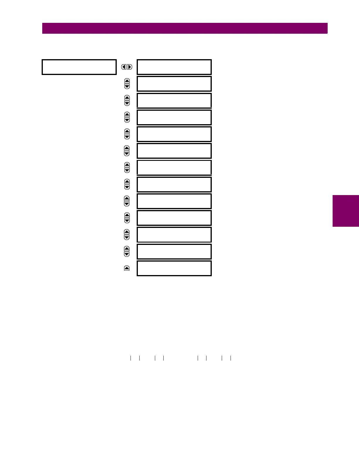
NEG SEQ DIR OC1
NEG SEQ DIR OC1
FUNCTION: Disabled
Range: Disabled, Enabled
MESSAGE
NEG SEQ DIR OC1
SOURCE: SRC 1
Range: SRC 1, SRC 2, SRC 3, SRC 4
MESSAGE
NEG SEQ DIR OC1
OFFSET: 0.00 Ω
Range: 0.00 to 250.00 ohms in steps of 0.01
MESSAGE
NEG SEQ DIR OC1
TYPE: Neg Sequence
Range: Neg Sequence, Zero Sequence
MESSAGE
NEG SEQ DIR OC1 POS-
SEQ RESTRAINT: 0.063
Range: 0.000 to 0.500 in steps of 0.001
MESSAGE
NEG SEQ DIR OC1 FWD
ECA: 75° Lag
Range: 0 to 90° Lag in steps of 1
MESSAGE
NEG SEQ DIR OC1 FWD
LIMIT ANGLE: 90°
Range: 40 to 90° in steps of 1
MESSAGE
NEG SEQ DIR OC1 FWD
PICKUP: 0.050 pu
Range: 0.015 to 30.000 pu in steps of 0.001
MESSAGE
NEG SEQ DIR OC1 REV
LIMIT ANGLE: 90°
Range: 40 to 90° in steps of 1
MESSAGE
NEG SEQ DIR OC1 REV
PICKUP: 0.050 pu
Range: 0.015 to 30.000 pu in steps of 0.001
MESSAGE
NEG SEQ DIR OC1 BLK:
Off
Range: FlexLogic™ operand
MESSAGE
NEG SEQ DIR OC1
TARGET: Self-reset
Range: Self-reset, Latched, Disabled
MESSAGE
NEG SEQ DIR OC1
EVENTS: Disabled
Range: Disabled, Enabled
I
op
I_2 K I_1×–= or I
op
I_0 K I_1×–=

 Loading...


