5-182 L60 Line Phase Comparison System GE Multilin
5.5 GROUPED ELEMENTS 5 SETTINGS
5
The positive-sequence restraint must be considered when testing for pick-up accuracy and response time (multiple of
pickup). The operating quantity depends on the way the test currents are injected into the relay:
• Single-phase injection: I
op
= 1/3 × (1 – K)×I
injected
.
• Three-phase pure zero- or negative-sequence injection, respectively: I
op
= I
injected
.
• The directional unit uses the negative-sequence current and voltage for fault direction discrimination.
The following table defines the negative-sequence directional overcurrent element.
The negative-sequence voltage must be higher than the
PRODUCT SETUP ÖØ DISPLAY PROPERTIES ÖØ VOLTAGE CUT-OFF
LEVEL value to be validated for use as a polarizing signal. If the polarizing signal is not validated neither forward nor reverse
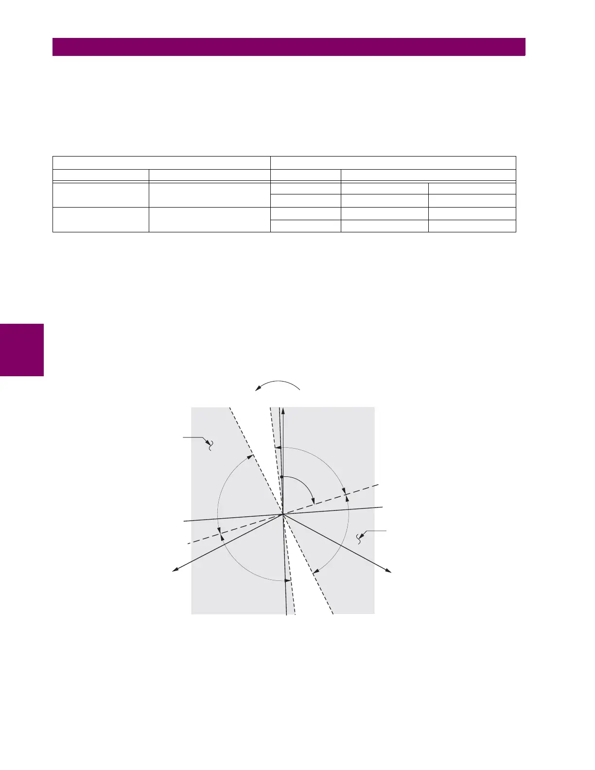
indication is given. The following figure explains the usage of the voltage polarized directional unit of the element.
The figure below shows the phase angle comparator characteristics for a phase A to ground fault, with settings of:
ECA = 75° (element characteristic angle = centerline of operating characteristic)
FWD LA = 80° (forward limit angle = ± the angular limit with the ECA for operation)
REV LA = 80° (reverse limit angle = ± the angular limit with the ECA for operation)
The element incorporates a current reversal logic: if the reverse direction is indicated for at least 1.25 of a power system
cycle, the prospective forward indication will be delayed by 1.5 of a power system cycle. The element is designed to emu-
late an electromechanical directional device. Larger operating and polarizing signals will result in faster directional discrimi-
nation bringing more security to the element operation.
Figure 5–97: NEGATIVE-SEQUENCE DIRECTIONAL CHARACTERISTIC
The forward-looking function is designed to be more secure as compared to the reverse-looking function, and therefore
should be used for the tripping direction. The reverse-looking function is designed to be faster as compared to the forward-
looking function and should be used for the blocking direction. This allows for better protection coordination. The above
bias should be taken into account when using the negative-sequence directional overcurrent element to directionalize other
protection elements.
OVERCURRENT UNIT DIRECTIONAL UNIT
MODE OPERATING CURRENT DIRECTION COMPARED PHASORS
Negative-sequence
I
op
= |I_2| – K × I_1|
Forward –V_2 + Z_offset × I_2 I_2 × 1∠ECA
Reverse –V_2 + Z_offset × I_2 –(I_2 × 1∠ECA)
Zero-sequence
I
op
= |I_0| – K × |I_1|
Forward –V_2 + Z_offset × I_2 I_2 × 1∠ECA
Reverse –V_2 + Z_offset × I_2 –(I_2 × 1∠ECA)
827806A2.CDR
VAG (reference)
VCG
VBG
–I_2 line
I_2 line
ECA line
–ECA line
LA
LA
LA
LA ECA
FWD Operating
Region
REV Operating
Region
FWD
LA
FWD
LA
REV
LA
REV
LA
V_2 line
–V_2 line

 Loading...


