GE Multilin T60 Transformer Protection System 2-1
2 PRODUCT DESCRIPTION 2.1 INTRODUCTION
2
2 PRODUCT DESCRIPTION 2.1INTRODUCTION 2.1.1 OVERVIEW
The T60 Transformer Protection System is a microprocessor-based relay for protection of small, medium, and large three-
phase power transformers. The relay can be configured with a maximum of four three-phase current inputs and four ground
current inputs, and can satisfy applications with transformer windings connected between two breakers, such as in a ring
bus or in breaker-and-a-half configurations. The T60 performs magnitude and phase shift compensation internally, eliminat-
ing requirements for external CT connections and auxiliary CTs.
The percent differential element is the main protection device in the T60. Instantaneous differential protection, volts-per-
hertz, restricted ground fault, and many current, voltage, and frequency-based protection elements are also incorporated.
The T60 includes sixteen fully programmable universal comparators, or FlexElements™, that provide additional flexibility
by allowing the user to customize their own protection functions that respond to any signals measured or calculated by the
relay.
The metering functions of the T60 include true RMS and phasors for currents and voltages, current harmonics and THD,
symmetrical components, frequency, power, power factor, and energy.
Diagnostic features include an event recorder capable of storing 1024 time-tagged events, oscillography capable of storing
up to 64 records with programmable trigger, content and sampling rate, and data logger acquisition of up to 16 channels,
with programmable content and sampling rate. The internal clock used for time-tagging can be synchronized with an IRIG-
B signal or via the SNTP protocol over the Ethernet port. This precise time stamping allows the sequence of events to be
determined throughout the system. Events can also be programmed (via FlexLogic™ equations) to trigger oscillography
data capture which may be set to record the measured parameters before and after the event for viewing on a personal
computer (PC). These tools significantly reduce troubleshooting time and simplify report generation in the event of a sys-
tem fault.
A faceplate RS232 port may be used to connect to a PC for the programming of settings and the monitoring of actual val-
ues. A variety of communications modules are available. Two rear RS485 ports allow independent access by operating and
engineering staff. All serial ports use the Modbus
®
RTU protocol. The RS485 ports may be connected to system computers
with baud rates up to 115.2 kbps. The RS232 port has a fixed baud rate of 19.2 kbps. Optional communications modules
include a 10/100Base-F Ethernet interface which can be used to provide fast, reliable communications in noisy environ-
ments. Another option provides two 10/100Base-F fiber optic ports for redundancy. The Ethernet port supports IEC 61850,
Modbus
®
/TCP, and TFTP protocols, and allows access to the relay via any standard web browser (T60 web pages). The
IEC 60870-5-104 protocol is supported on the Ethernet port. DNP 3.0 and IEC 60870-5-104 cannot be enabled at the same
time.
Settings and actual values can be accessed from the front panel or EnerVista software.
The T60 IEDs use flash memory technology that allows field upgrading as new features are added.
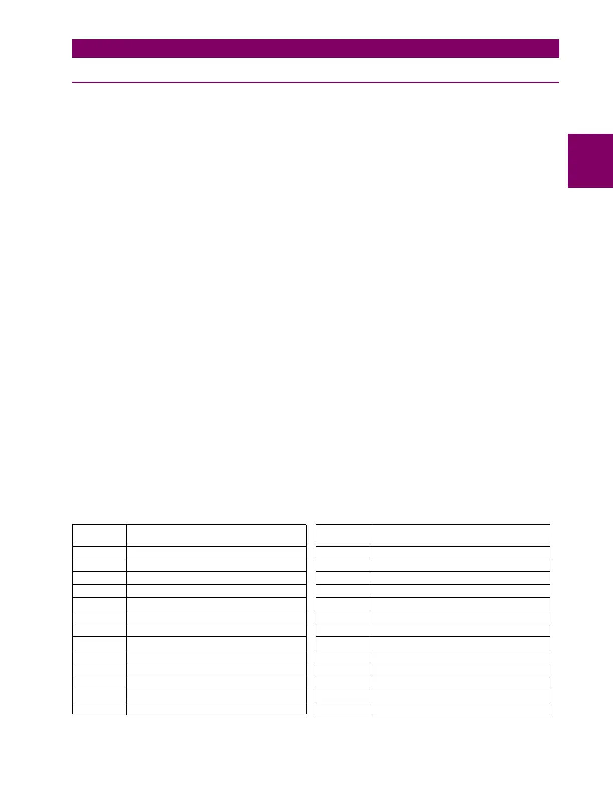
The following Single line diagram illustrates the relay functionality using ANSI (American National Standards Institute)
device numbers.
Table 2–1: ANSI DEVICE NUMBERS AND FUNCTIONS
DEVICE
NUMBER
FUNCTION DEVICE
NUMBER
FUNCTION
21G Ground distance 51N Neutral time overcurrent
21P Phase distance 51P Phase time overcurrent
24 Volts per hertz 59N Neutral overvoltage
25 Synchrocheck (optional) 59P Phase overvoltage
27P Phase undervoltage 59X Auxiliary overvoltage
27X Auxiliary undervoltage 67N Neutral directional overcurrent
49 Thermal overload protection 67P Phase directional overcurrent
50/87 Instantaneous differential overcurrent 68 Power swing blocking
50BF Breaker failure 78 Out-of-step tripping
50G Ground instantaneous overcurrent 81O Overfrequency
50N Neutral instantaneous overcurrent 81U Underfrequency
50P Phase instantaneous overcurrent 87G Restricted ground fault
51G Ground time overcurrent 87T Transformer differential