GE Multilin T60 Transformer Protection System 5-105
5 SETTINGS 5.4 SYSTEM SETUP
5
5.4.8 PHASOR MEASUREMENT UNIT
a) MAIN MENU
PATH: SETTINGS SYSTEM SETUP PHASOR MEASUREMENT UNIT
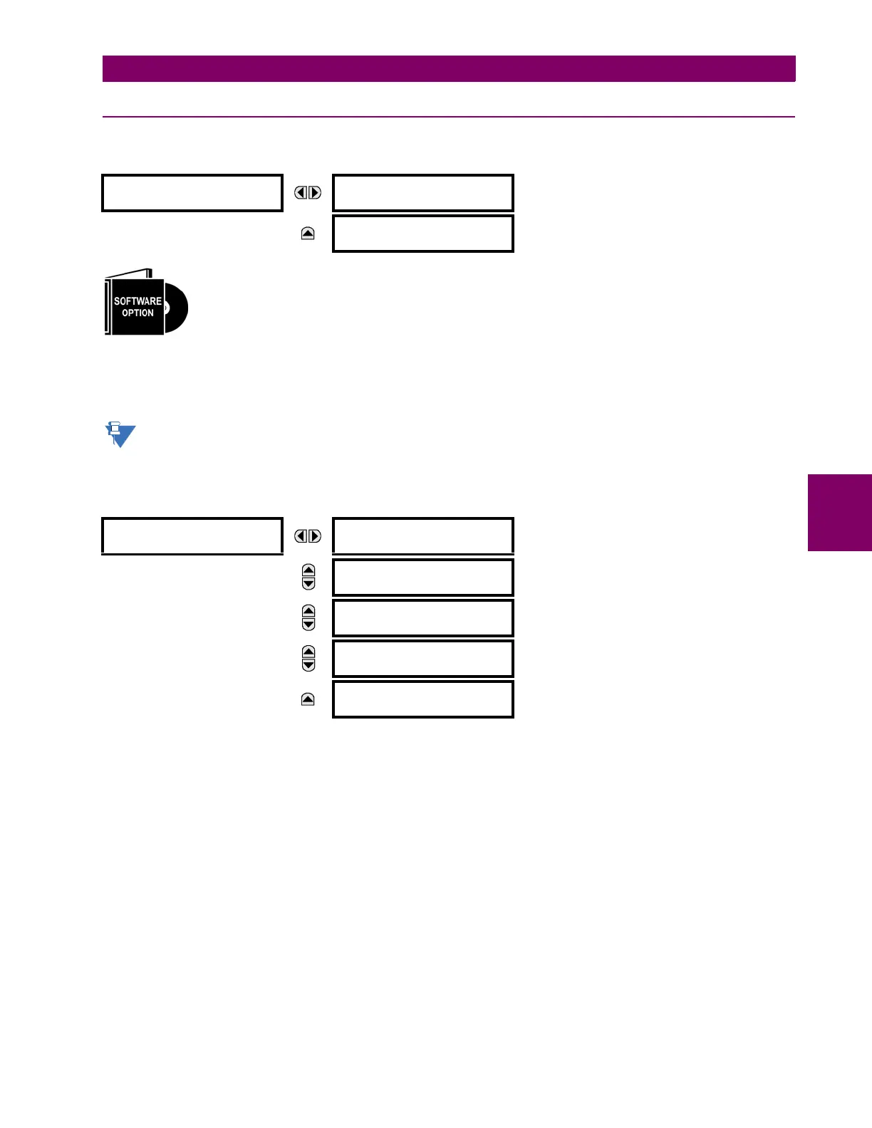
The T60 Transformer Protection System is provided with an optional phasor measurement unit feature.
This feature is specified as a software option at the time of ordering. The number of phasor measurement
units available is also dependent on this option. Refer to the Ordering section of chapter 2 for additional
details.
The
PHASOR MEASUREMENT UNIT menu allows specifying basic parameters of the measurements process such as signal
source, ID and station name, calibration data, triggering, recording, and content for transmission on each of the supported
ports. The reporting ports menus allow specifying the content and rate of reporting on each of the supported ports.
Precise IRIG-B input is vital for correct synchrophasor measurement and reporting. A DC level shift IRIG-B receiver
must be used for the phasor measurement unit to output proper synchrophasor values.
The PMU settings are organized in logical groups as follows.
PATH: SETTINGS SYSTEM SETUP PHASOR MEASUREMENT UNIT PHASOR MEASUREMENT UNIT 1
PHASOR MEASUREMENT
UNIT
PHASOR MEASUREMENT
UNIT 1
See below.
MESSAGE
REPORTING OVER
NETWORK
See page 5-120.
PHASOR MEASUREMENT
UNIT 1
PMU 1 BASIC
CONFIGURATION
See page 5-106.
MESSAGE
PMU 1
CALIBRATION
See page 5-107.
MESSAGE
PMU 1
COMMUNICATION
See page 5-108.
MESSAGE
PMU 1
TRIGGERING
See page 5-110.
MESSAGE
PMU 1
RECORDING
See page 5-117.